Imaging optical system having bending optical element

a technology of optical elements and imaging optical systems, applied in the field of imaging optical systems having bending optical elements, to achieve the effect of reducing the thickness of imaging optical systems

Active Publication Date: 2015-04-16
HOYA CORP
View PDF2 Cites 18 Cited by
  • Summary
  • Abstract
  • Description
  • Claims
  • Application Information

AI Technical Summary

Benefits of technology

[0007]Based on the above described technical background, the present invention provides an imaging optical system having one or more bending optical elements, wherein the imaging optical system makes it possible to strike a balance between a reduction in F-number and a further reduction in thickness of the imaging optical system.
[0009]The present invention concentrates on the shape of an effective optical surface of a large-diameter lens element having the greatest axial light-bundle effective radius among the lens elements that lie on a post-bending optical axis of an imaging optical system; accordingly, the present invention has been devised from the viewpoint that it is possible to reduce the thickness of the imaging optical system while suppressing deterioration of the optical performance thereof via image processing if the large-diameter lens element is formed into an irregular shape (non-circular shape) by making the length of the effective optical surface from the post-bending optical axis toward the side opposite from the object side smaller than the axial light bundle effective radius, with reference to the axial light bundle effective radius lying on a plane which includes the post-bending optical axis and extends orthogonal to a plane including both the post-bending optical axis and the pre-bending optical axis of the imaging optical system. If an effective optical surface of a large-diameter lens element is formed into a non-circular shape, the light bundle incident on an imaging surface becomes asymmetrical, so that a difference in resolving power theoretically occurs between each direction (vertical and horizontal directions). However, no practical problems occur if aberrations are sufficiently corrected, and the problem of peripheral light quantity being asymmetrical can also be corrected by image processing. Additionally, in imaging optical systems, a negative or positive lens element can usually be arranged in front of a bending optical element (on the object side thereof), so that the length of a lens group in the post-bending optical system from the optical axis thereof toward the object side also does not have to be sacrificed.
[0024]In other words, the imaging optical system according to the present invention achieves a reduction in thickness thereof is achieved while a desired lens speed (F-number) is obtained (in other words, the lens speed is not sacrificed) by setting the shape of an effective optical surface of the irregular-shaped large-diameter lens element so that, with reference to the area of a circular-shaped entrance pupil for obtaining a desired lens speed (F-number), the area of the irregular-shaped entrance pupil becomes identical to the area of this circular-shaped entrance pupil. Namely, an imaging optical system identical in lens speed to that having a circular entrance pupil can be obtained by satisfying “(the area of the entrance pupil formed by an axial light bundle through a circular aperture)=(the area of the entrance pupil formed by an axial light bundle through an irregular-shaped aperture).” In this connection, in order to use an F-number definition in an optical system having an irregular-shaped aperture, the F-number is calculated from the diameter of the aforementioned reference circular entrance pupil since the F-number is equal to the focal length divided by the entrance pupil diameter (F-number=focal length / entrance pupil diameter).
[0031]The present invention achieves both a reduction in F-number and a further reduction in thickness of the imaging optical system by providing a bending optical system which bends alight bundle emanating from an object, a post-bending lens system which is positioned on a post-bending optical axis that is defined by the optical axis of the imaging optical system being bent by the bending optical element, and an image sensor on which an image of the object is formed via the post-bending lens system; and by the outer shape of an effective optical surface of an irregular-shaped large-diameter lens group, the axial light bundle effective radius of which is the greatest among all the lens elements of the post-bending lens system, being formed to be non-circular as viewed in the direction of the post-bending optical axis.

Problems solved by technology

However, no practical problems occur if aberrations are sufficiently corrected, and the problem of peripheral light quantity being asymmetrical can also be corrected by image processing.

Method used


Image

  • Imaging optical system having bending optical element
  • Imaging optical system having bending optical element
  • Imaging optical system having bending optical element

Examples


Embodiment Construction

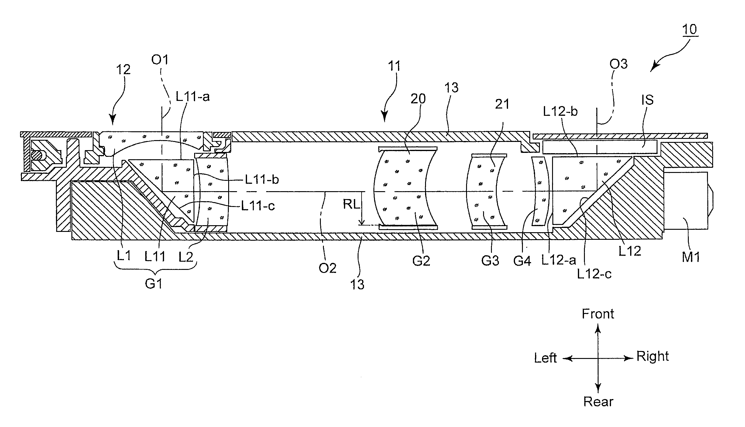
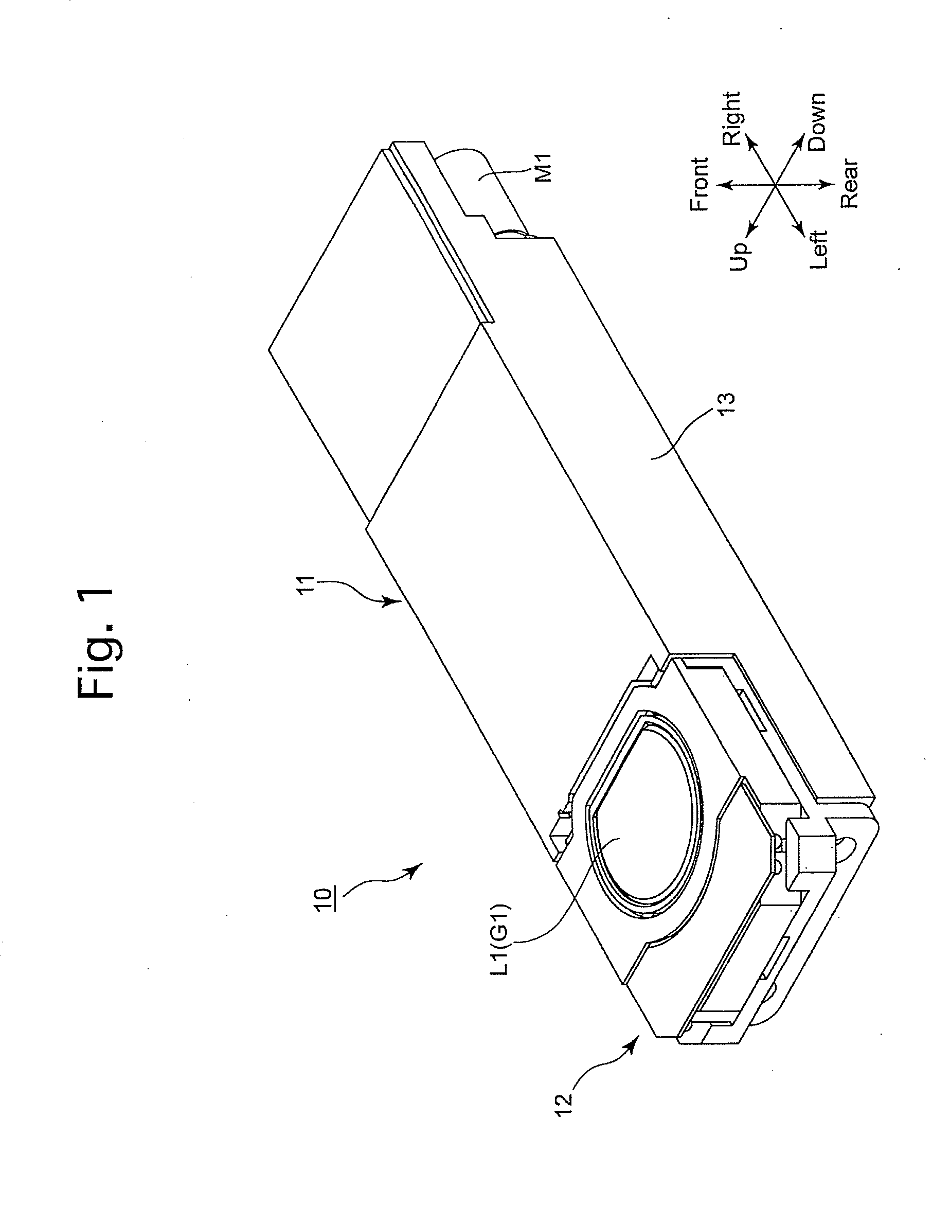
[0040]An embodiment of an imaging unit (imaging apparatus) 10 according to the present invention will be discussed below with reference to FIGS. 1 through 6. In the following descriptions, forward and rearward directions, leftward and rightward directions, and upward and downward directions are determined with reference to the directions of the double-headed arrows shown in FIGS. 1 through 6. The object side corresponds to the front side. As shown by the outward appearance of the imaging unit 10 in FIG. 1, the imaging unit 10 has a laterally elongated shape which is slim in the forward / rearward direction and long in the leftward / rightward direction.

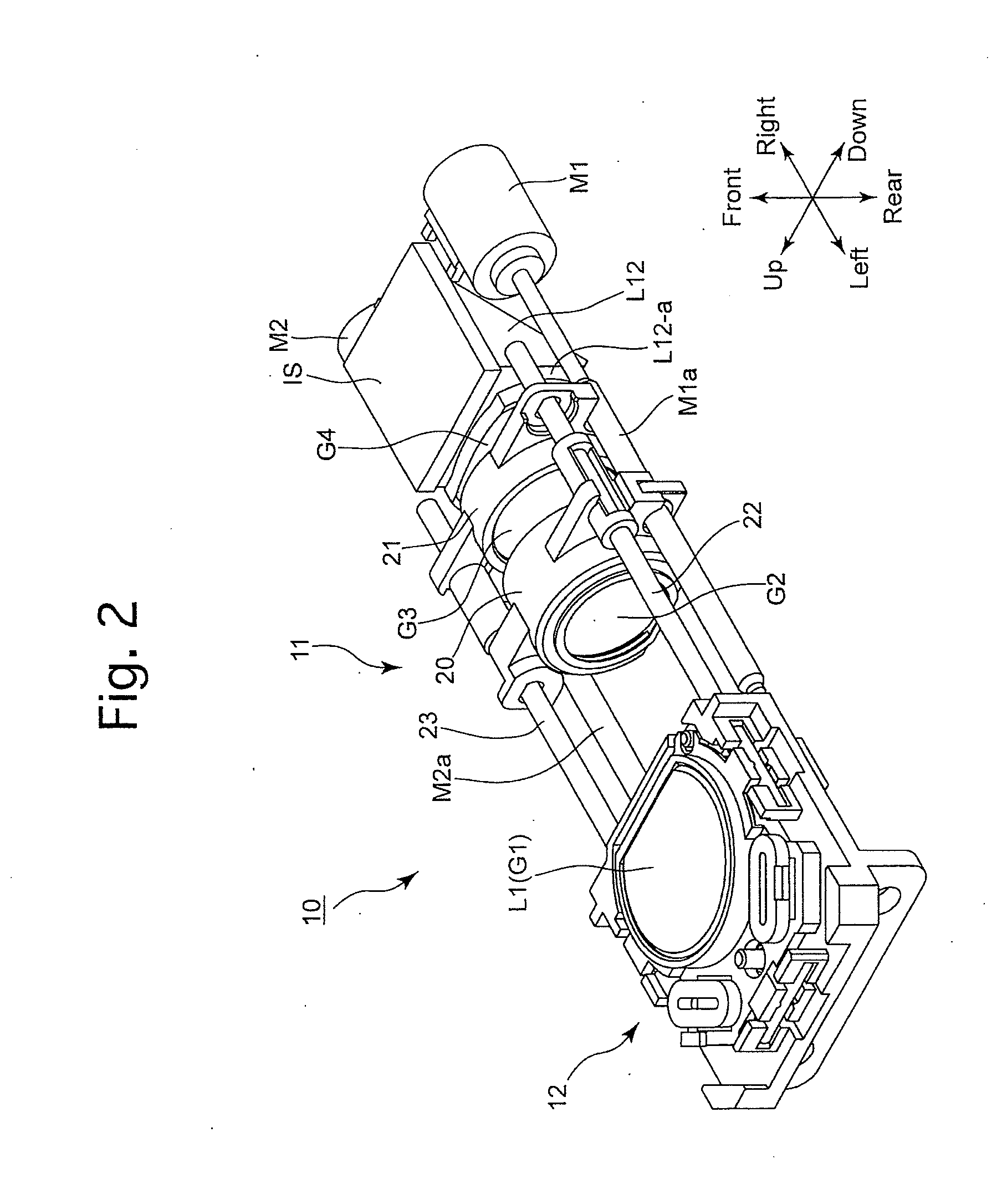
[0041]As shown in FIGS. 2 and 3, the imaging unit 10 has an imaging optical system which is provided with a first lens group G1, a second lens group (post-bending optical system) G2, a third lens group (post-bending optical system) G3 and a fourth lens group (post-bending optical system) G4. The first lens group G1 is provided with a firs...


PUM


Abstract

An imaging optical system includes a bending optical element which bends an object-emanating light bundle, a post-bending lens system on a post-bending optical axis defined by the bending optical element, and an image sensor. An effective optical surface of a large-diameter lens element, having a greatest axial light bundle effective radius, is formed into a non-circular shape by making a length of the effective optical surface from the post-bending optical axis toward a side opposite from the object side smaller than the axial light bundle effective radius, with reference to the axial light bundle effective radius lying on a plane which extends orthogonal to a plane including both the post-bending optical axis and a pre-bending optical axis of the imaging optical system and includes the post-bending optical axis.

Description

BACKGROUND OF THE INVENTION[0001]1. Field of the Invention[0002]The present invention relates to an imaging optical system having a bending optical element.[0003]2. Description of the Related Art[0004]In recent years, mobile electronic devices which are designed mainly for taking still / moving photographic images, such as digital cameras (still-video cameras) and digital camcorders (motion-video cameras), and other mobile electronic devices which are designed to be capable of taking such photographic images as a subsidiary function, such as mobile phones equipped with a camera and tablet computers, etc., equipped with a camera, have become widespread, and there has been a demand to miniaturize the imaging units incorporated in these types of mobile electronic devices. In order to miniaturize an imaging unit, it is known to configure an optical system of an imaging unit as a bending optical system which reflects (bends) a light bundle using a reflection surface of a reflecting element...

Claims


Application Information

Patent Timeline
Patent Type & Authority Applications(United States)
IPC IPC(8): G02B13/00G02B13/04
CPCG02B13/0065G02B13/0015G02B13/04G02B13/005
Inventor NOMURA, HIROSHITADA, EIJIROH
Owner HOYA CORP
Why Eureka
Try Eureka