Lens Assembly

a technology of lens assembly and lens body, which is applied in the field of lens assembly, can solve the problems that the known lens assembly cannot meet such requirements, and achieve the effects of reducing the f-number, good optical performance, and high resolution

Pending Publication Date: 2022-05-05
SINTAI OPTICAL (SHENZHEN) CO LTD IS A LARGE ENTITY +1
View PDF0 Cites 0 Cited by
  • Summary
  • Abstract
  • Description
  • Claims
  • Application Information

AI Technical Summary

Benefits of technology

[0003]The invention provides a lens assembly to solve the above problems. The lens assembly of the invention is provided with characteristics of a decreased f-number, a higher resolution, a resisted environmental temperature change, a same focus while day and night, and still has a good optical performance.

Problems solved by technology

However, the known lens assembly can't satisfy such requirements.

Method used


Image

  • Lens Assembly
  • Lens Assembly
  • Lens Assembly

Examples


first embodiment

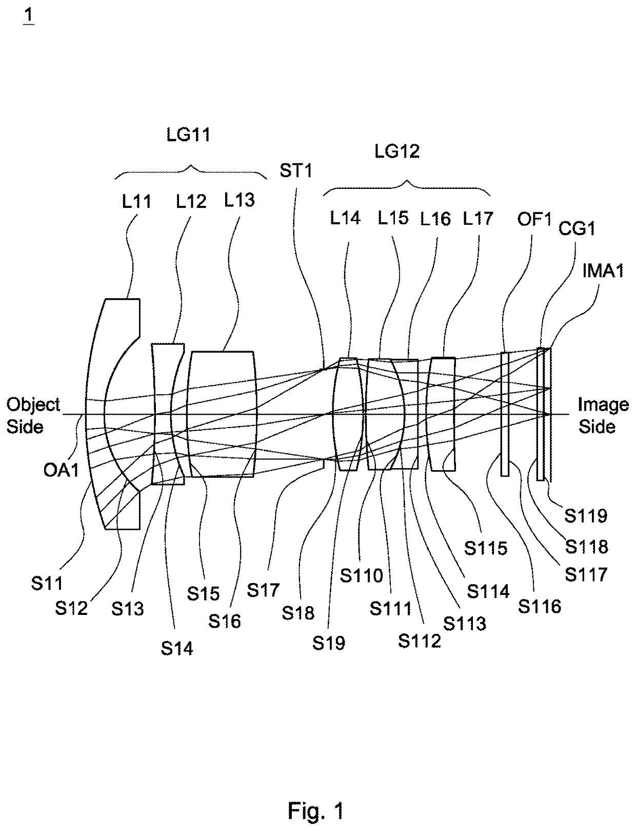
[0061]A detailed description of a lens assembly in accordance with the invention is as follows. Referring to FIG. 1, the lens assembly 1 includes a first lens group LG11, a stop ST1, a second lens group LG12, an optical filter OF1, and a cover glass CG1. The first lens group LG11 includes a first lens L11, a second lens L12 and a third lens L13 in order from an object side to an image side along an optical axis OA1. The second lens group LG12 includes a fourth lens L14, a fifth lens L15, a sixth lens L16 and a seventh lens L17 in order from the object side to the image side along the optical axis OA1. In operation, an image of light rays from the object side is formed at an image plane IMA1.

[0062]According to paragraphs [0037]-[0048], wherein: the second lens L12 is a biconcave lens, wherein the object side surface S13 is a concave surface, and both of the object side surface S13 and the image side surface S14 are spherical surface; the third lens L13 is a biconvex lens, wherein the...

second embodiment

[0069]Referring to FIG. 3, FIG. 3 is a lens layout and optical path diagram of a lens assembly in accordance with the invention. The lens assembly 2 includes a first lens group LG21, a stop ST2, a second lens group LG22, an optical filter OF2, and a cover glass CG2. The first lens group LG21 includes a first lens L21, a second lens L22 and a third lens L23 in order from an object side to an image side along an optical axis OA2. The second lens group LG22 includes a fourth lens L24, a fifth lens L25, a sixth lens L26 and a seventh lens L27 in order from the object side to the image side along the optical axis OA2. In operation, an image of light rays from the object side is formed at an image plane IMA2.

[0070]According to paragraphs [0037]-[0048], wherein: the second lens L22 is a meniscus lens, wherein the object side surface S23 is a convex surface, and both of the object side surface S23 and the image side surface S24 are aspheric surface; the third lens L23 is a meniscus lens, wh...

third embodiment

[0077]Referring to FIG. 5, FIG. 5 is a lens layout and optical path diagram of a lens assembly in accordance with the invention. The lens assembly 3 includes a first lens group LG31, a stop ST3, a second lens group LG32, an optical filter OF3, and a cover glass CG3. The first lens group LG31 includes a first lens L31, a second lens L32 and a third lens L33 in order from an object side to an image side along an optical axis OA3. The second lens group LG32 includes a fourth lens L34, a fifth lens L35, a sixth lens L36 and a seventh lens L37 in order from the object side to the image side along the optical axis OA3. In operation, an image of light rays from the object side is formed at an image plane IMA3.

[0078]According to paragraphs [0037]-[0048] wherein: the second lens L32 is a meniscus lens, wherein the object side surface S33 is a convex surface, and both of the object side surface S33 and the image side surface S34 are aspheric surface; the third lens L33 is a meniscus lens, whe...


PUM


Abstract

A lens assembly includes a first, second, third, stop, fourth, fifth, sixth, and seventh in order from an object side to an image side along an optical axis. The first lens is a meniscus lens with refractive power and includes a convex surface facing the object side and a concave surface facing the image side. The second lens is with negative refractive power. The third lens is with positive refractive power and includes a convex surface facing the image side. The fourth lens is with refractive power and includes a convex surface facing the image side. The fifth lens is with positive refractive power and includes a convex surface facing the object side. The sixth lens is a biconcave lens with negative refractive power. The seventh lens is with refractive power and includes a convex surface facing the image side. The lens assembly satisfies: 4.3≤TTL / BFL≤5.3.

Description

BACKGROUND OF THE INVENTIONField of the Invention[0001]The invention relates to a lens assembly.Description of the Related Art[0002]The current development trend of a lens assembly is toward large stop, high resolution, and resistance to environmental temperature change. In addition, it should also have the feature of day and night with the same focus, whether day or night to capture clear images, in order to meet the requirements of both day and night image quality. However, the known lens assembly can't satisfy such requirements. Therefore, the lens assembly needs a new structure in order to meet the requirements of large stop, high resolution, resistance to environmental temperature change, and with the same focus while day and night at the same time.BRIEF SUMMARY OF THE INVENTION[0003]The invention provides a lens assembly to solve the above problems. The lens assembly of the invention is provided with characteristics of a decreased f-number, a higher resolution, a resisted envi...

Claims


Application Information

Patent Timeline
Patent Type & Authority Applications(United States)
IPC IPC(8): G02B9/10G02B13/18G02B9/64
CPCG02B9/10G02B9/64G02B13/18G02B13/0045G02B7/008
Inventor LEE, JIAN-WEILIN, SHU-HUNG
Owner SINTAI OPTICAL (SHENZHEN) CO LTD IS A LARGE ENTITY
Why Eureka
Try Eureka