Optical imaging lens

a technology of optical imaging and lens, applied in the field of optical devices, can solve the problems of increasing distance, no avail for thinning mobile phones and digital cameras, etc., and achieve the effects of reducing the f-number (fno) reducing the system length of the optical imaging lens, and increasing the image heigh

Pending Publication Date: 2022-06-23
GENIUS ELECTRONICS OPTICAL XIAMEN
View PDF0 Cites 0 Cited by
  • Summary
  • Abstract
  • Description
  • Claims
  • Application Information

AI Technical Summary

Benefits of technology

[0005]The disclosure provides an optical imaging lens, which has a larger image height and meanwhile shortens a system length of the optical imaging lens and reduces an f-number (Fno) of the optical imaging lens.

Problems solved by technology

However, increasing the number of optical lens elements in response to the demands also increases the distance between the object-side surface of a first lens element and the image plane on the optical axis, which is of no avail for thinning the mobile phones and digital cameras.

Method used


Image

  • Optical imaging lens
  • Optical imaging lens
  • Optical imaging lens

Examples


first embodiment

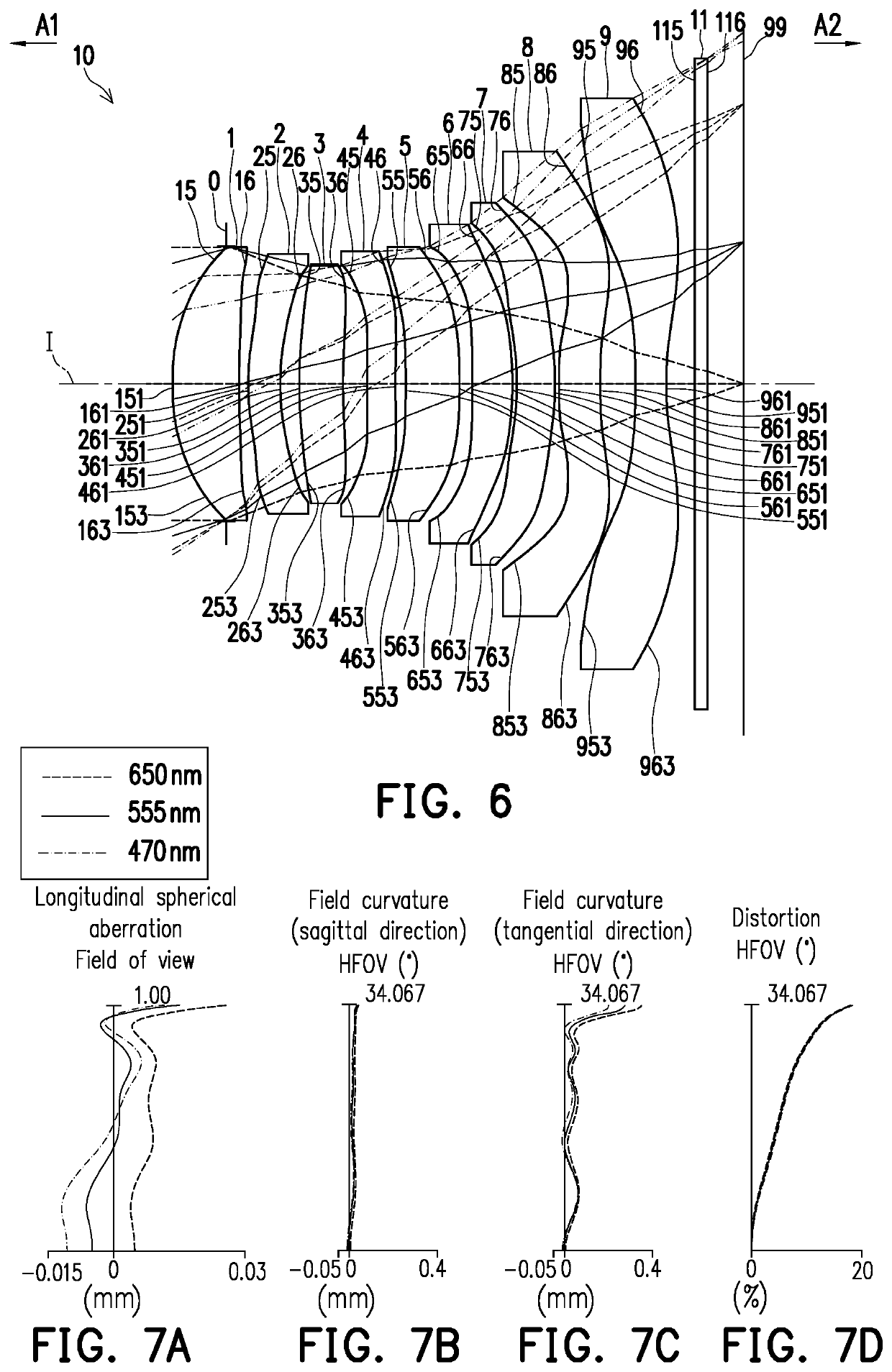
[0098]In addition, a relationship between important parameters in the optical imaging lens 10 of the first embodiment is as shown in FIG. 50 and FIG. 51.

[0099]Where,

[0100]f1 is a focal length of the first lens element;

[0101]f2 is a focal length of the second lens element;

[0102]f3 is a focal length of the third lens element;

[0103]f4 is a focal length of the fourth lens element;

[0104]f5 is a focal length of the fifth lens element;

[0105]f6 is a focal length of the sixth lens element;

[0106]f7 is a focal length of the seventh lens element;

[0107]f8 is a focal length of the eighth lens element;

[0108]f9 is a focal length of the ninth lens element;

[0109]n1 is a refractive index of the first lens element;

[0110]n2 is a refractive index of the second lens element;

[0111]n3 is a refractive index of the third lens element;

[0112]n4 is a refractive index of the fourth lens element;

[0113]n5 is a refractive index of the fifth lens element;

[0114]n6 is a refractive index of the sixth lens element;

[0115]...

second embodiment

[0160]As shown in FIG. 13, FIG. 13 illustrates various aspheric coefficients of the object-side surface 15 of the first lens element 1 to the image-side surface 96 of the ninth lens element 9 of the second embodiment in the above equation (1).

[0161]In addition, a relationship between important parameters in the optical imaging lens 10 of the second embodiment is shown in FIG. 50 and FIG. 51.

[0162]The longitudinal spherical aberration of the second embodiment is as shown in FIG. 11A, and the deviation of the imaging points of the off-axis rays of different heights is controlled within a range of ±0.018 mm. In the two field curvature aberration diagrams of FIG. 11B and FIG. 11C, a focal length variation of the three representative wavelengths within the entire field of view range falls within ±0.06 mm. The distortion aberration diagram in FIG. 11D shows that the distortion aberration of the embodiment is maintained within a range of ±6%.

[0163]From the above description, it is known th...

third embodiment

[0166]As shown in FIG. 17, FIG. 17 illustrates various aspheric coefficients of the object-side surface 15 of the first lens element 1 to the image-side surface 96 of the ninth lens element 9 of the third embodiment in the above equation (1).

[0167]In addition, a relationship between important parameters in the optical imaging lens 10 of the third embodiment is shown in FIG. 50 and FIG. 51.

[0168]The longitudinal spherical aberration of the third embodiment is as shown in FIG. 15A, and the deviation of the imaging points of the off-axis rays of different heights is controlled within a range of ±0.06 mm. In the two field curvature aberration diagrams of FIG. 15B and FIG. 15C, a focal length variation of the three representative wavelengths within the entire field of view range falls within ±0.07 mm. The distortion aberration diagram in FIG. 15D shows that the distortion aberration of the embodiment is maintained within a range of ±2.5%.

[0169]From the above description, it is known that...


PUM


Abstract

An optical imaging lens sequentially including a first lens element to a ninth lens element arranged in sequence from an object side to an image side along an optical axis is provided. Each of the first lens element to the ninth lens element includes an object-side surface facing the object-side surface and allowing imaging rays to pass through and an image-side surface facing the image-side and allowing the imaging rays to pass through. Lens elements of the optical imaging lens are only the nine lens elements described above, wherein the second lens element has negative refracting power, the fourth lens element has negative refracting power, an optical axis region of the object-side surface of the seventh lens element is concave, and an optical axis region of the image-side surface of the ninth lens element is concave.

Description

CROSS REFERENCE TO RELATED APPLICATION[0001]This application claims the priority benefit of China application serial no. 202011503681.5, filed on Dec. 18, 2020. The entirety of the above-mentioned patent application is hereby incorporated by reference herein and made a part of specification.BACKGROUNDTechnical Field[0002]The disclosure relates to an optical device, and particularly to an optical imaging lens.Description of Related Art[0003]In recent years, optical imaging lenses have been evolving continuously. In addition to providing compact and slim optical imaging lenses, it is also increasingly important to improve the imaging quality of the lenses, such as mitigating optical aberration, chromatic aberration, etc. However, increasing the number of optical lens elements in response to the demands also increases the distance between the object-side surface of a first lens element and the image plane on the optical axis, which is of no avail for thinning the mobile phones and digi...

Claims


Application Information

Patent Timeline
Patent Type & Authority Applications(United States)
IPC IPC(8): G02B13/00G02B9/64G02B27/00
CPCG02B13/0045G02B27/0025G02B9/64G02B13/0015
Inventor JHANG, JIA-SINCHEN, YANBIN
Owner GENIUS ELECTRONICS OPTICAL XIAMEN
Why Eureka
Try Eureka