Optical imaging lens

a technology of optical imaging and lens, applied in the field of optical imaging lenses, can solve the problems of increasing design difficulty, increasing design difficulty, increasing aperture and image height, etc., and achieves the effects of shortening system length, reducing design difficulty, and reducing design difficulty

Pending Publication Date: 2022-05-26
GENIUS ELECTRONICS OPTICAL XIAMEN
View PDF0 Cites 0 Cited by
  • Summary
  • Abstract
  • Description
  • Claims
  • Application Information

AI Technical Summary

Benefits of technology

[0005]In light of the above, the present invention proposes an optical imaging lens of seven lens elements which has shorter system length, smaller f-number, larger image height, good imaging quality and technically possible. The optical imaging lens of seven lens elements of the present invention from an object side to an image side in order along an optical axis has a first lens element, a second lens element, a third lens element, a fourth lens element, a fifth lens element, a sixth lens element and a seventh lens element. Each first lens element, second lens element, third lens element, fourth lens element, fifth lens element, sixth lens element and seventh lens element respectively has an object-side surface which faces toward the object side to allow imaging rays to pass through as well as an image-side surface which faces toward the image side to allow the imaging rays to pass through.

Problems solved by technology

However, the design of large f-number makes the lens accept more imaging light, which makes the design more difficult.
The high pixel makes the resolution of the optical imaging lens improve, and the design difficulty is increased with the large aperture design.
Therefore, how to add multiple lens elements to the limited system length, improve the resolution, increase the aperture and the image height at the same time, is a problem that needs to be challenged and solved.

Method used


Image

  • Optical imaging lens
  • Optical imaging lens
  • Optical imaging lens

Examples


first embodiment

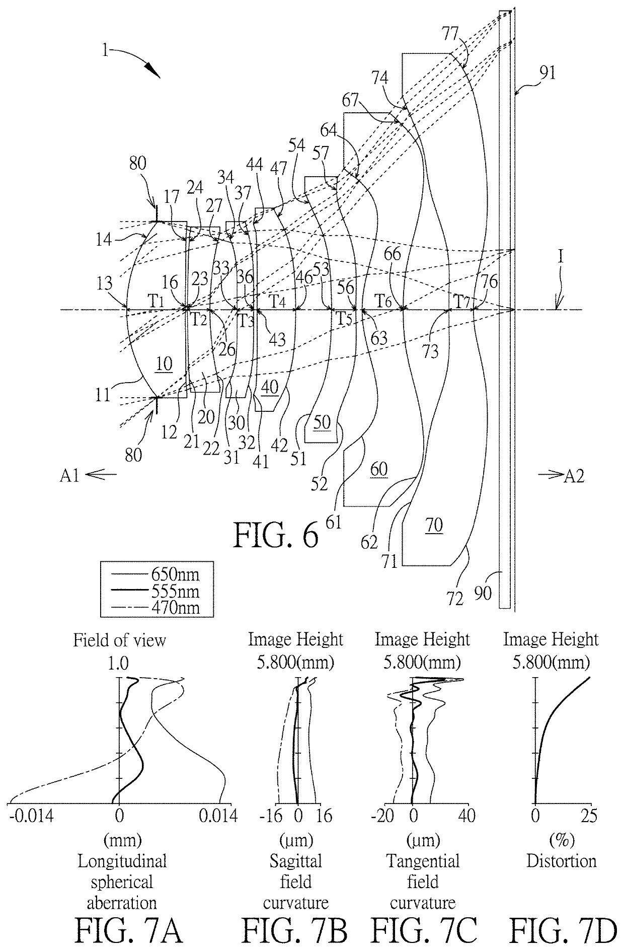
[0119]Please refer to FIG. 6 which illustrates the first embodiment of the optical imaging lens 1 of the present invention. Please refer to FIG. 7A for the longitudinal spherical aberration on the image plane 91 of the first embodiment; please refer to FIG. 7B for the field curvature aberration on the sagittal direction; please refer to FIG. 7C for the field curvature aberration on the tangential direction; and please refer to FIG. 7D for the distortion aberration. The Y axis of the spherical aberration in each embodiment is “field of view” for 1.0. The Y axis of each aberration and the distortion in each embodiment stands for “image height” (ImgH), and the image height of the first embodiment is 5.800 mm.

[0120]Only the seven lens elements 10, 20, 30, 40, 50, 60 and 70 of the optical imaging lens 1 of the first embodiment have refracting power. The optical imaging lens 1 also has an aperture stop 80, a filter 90, and an image plane 91. The aperture stop 80 is provided between the ob...

second embodiment

[0136]Please refer to FIG. 8 which illustrates the second embodiment of the optical imaging lens 1 of the present invention. It is noted that from the second embodiment to the following embodiments, in order to simplify the figures, only the components different from what the first embodiment has, and the basic lens elements will be labeled in figures. Other components that are the same as what the first embodiment has, such as the object-side surface, the image-side surface, the optical axis region and the periphery region will be omitted in the following embodiments. Please refer to FIG. 9A for the longitudinal spherical aberration on the image plane 91 of the second embodiment, please refer to FIG. 9B for the field curvature aberration on the sagittal direction, please refer to FIG. 9C for the field curvature aberration on the tangential direction, and please refer to FIG. 9D for the distortion aberration. The components in this embodiment are similar to those in the first embodi...

third embodiment

[0138]Please refer to FIG. 10 which illustrates the third embodiment of the optical imaging lens 1 of the present invention. Please refer to FIG. 11A for the longitudinal spherical aberration on the image plane 91 of the third embodiment; please refer to FIG. 11B for the field curvature aberration on the sagittal direction; please refer to FIG. 11C for the field curvature aberration on the tangential direction; and please refer to FIG. 11D for the distortion aberration. The components in this embodiment are similar to those in the first embodiment, but the optical data such as the radius of curvature, the lens thickness, the aspheric surface or the back focal length in this embodiment are different from the optical data in the first embodiment. In addition, in this embodiment, the optical axis region 33 of the object-side surface 31 of the third lens element 30 is convex, the periphery region 37 of the image-side surface 32 of the third lens element 30 is concave, the optical axis r...


PUM


Abstract

An optical imaging lens includes a first lens element to a seventh lens element, and each lens element has an object-side surface and an image-side surface. The second lens element has negative refracting power, an optical axis region of the object-side surface of the fifth lens element is concave, and an optical axis region of the object-side surface of the seventh lens element is convex. Lens elements included by the optical imaging lens are only the seven lens elements described above, and the following relationships: V5+V6+V7≥140.000, (ImgH+D61t72)/D11t42≥2.400, V4≥30.000 are satisfied.

Description

BACKGROUND OF THE INVENTION[0001]1. Field of the Invention[0002]The present invention generally relates to an optical imaging lens. Specifically speaking, the present invention is directed to an optical imaging lens for use in a portable electronic device such as a mobile phone, a camera, a tablet personal computer, or a personal digital assistant (PDA) for taking pictures or for recording videos.[0003]2. Description of the Prior Art[0004]The specifications of portable electronic products are changing with each passing day, and one of its key components: the optical imaging lens is also developing more diversified. For the main lens element of the portable electronic device, it not only requires a larger f-number and maintains a shorter system length, but also pursues higher pixels and higher resolution. The high pixel implies that the image height of the lens element must be increased, and the pixel demand can be increased by adopting a larger image sensor to receive the imaging li...

Claims


Application Information

Patent Timeline
Patent Type & Authority Applications(United States)
IPC IPC(8): G02B13/00G02B9/64
CPCG02B13/0045G02B9/64G02B13/0015
Inventor JHANG, JIA-SINHU, RUN
Owner GENIUS ELECTRONICS OPTICAL XIAMEN
Why Eureka
Try Eureka