Lens for projection and projection-type display apparatus

a technology of projection and display apparatus, applied in the field of projection and projection type display apparatus, can solve the problems of not meeting such a demand, affecting the size of the projection lens, and the power balance of the lens constituting each, so as to reduce the generation of aberrations, increase the size of the apparatus, and fast lens

Active Publication Date: 2012-03-29
FUJIFILM CORP
View PDF0 Cites 8 Cited by
  • Summary
  • Abstract
  • Description
  • Claims
  • Application Information

AI Technical Summary

Benefits of technology

[0046]According to a lens for projection of the present invention and a projection-type display apparatus of the present invention, the lens for projection substantially consists of five lenses. Further, a negative first lens having a concave surface facing the reduction side of the lens for projection, a positive second lens having a convex surface facing the magnification side of the lens for projection, a negative third lens having a concave surface facing the magnification side, a positive fourth lens having a convex surface facing the reduction side, and a positive fifth lens are arranged in this order from the magnification side. Further, formulas (A) through (D) are satisfied at the same time. Therefore, it is possible to obtain a lens having a smaller F-number (faster lens) while suppressing generation of aberrations and an increase in the size of an apparatus to a large size.
[0047]Specifically, in the present invention, the arrangement of positive and negative lenses (power balance) is appropriately set as described above. Therefore, it is possible to maintain the balance of aberrations in an excellent manner while constituting the lens for projection using a small number of lenses (five lenses). Further, it is possible to provide a lens for projection that has a small F-number (fast lens) without causing the size of an apparatus to become large. Therefore, it is possible to obtain a lens for projection that is small in size and light in weight, and that has high performance.

Problems solved by technology

However, projectors in which lenses for projection having relatively large F-numbers, as disclosed in Patent Documents 1 through 6, are mounted do not meet such a demand.
Specifically, the lenses for projection (F-number: 2.0 through 5.6) disclosed in Patent Documents 1 through 6 have problems in the power balance of lenses constituting each of the lenses for projection.
Therefore, If the F-number of the lens for projection is tried to be reduced (faster lens), aberrations are insufficiently corrected, or the size of the lens for projection becomes large.

Method used


Image

  • Lens for projection and projection-type display apparatus
  • Lens for projection and projection-type display apparatus
  • Lens for projection and projection-type display apparatus

Examples


specific examples

[0131]With reference to FIGS. 4 through 6, FIGS. 7A-7D through 9A-9D, FIGS. 10 through 13, and FIGS. 14A-14D through 17A-17D, and Tables 1 through 8, Examples 1-1 through 1-3 of the lens for projection of the present invention and Comparative Examples 1 through 4, which are outside the range of the present invention, and numerical data or the like thereof will be described together.

[0132]Examples 1-1 through 1-3 satisfy all of the formulas (A) through (G).

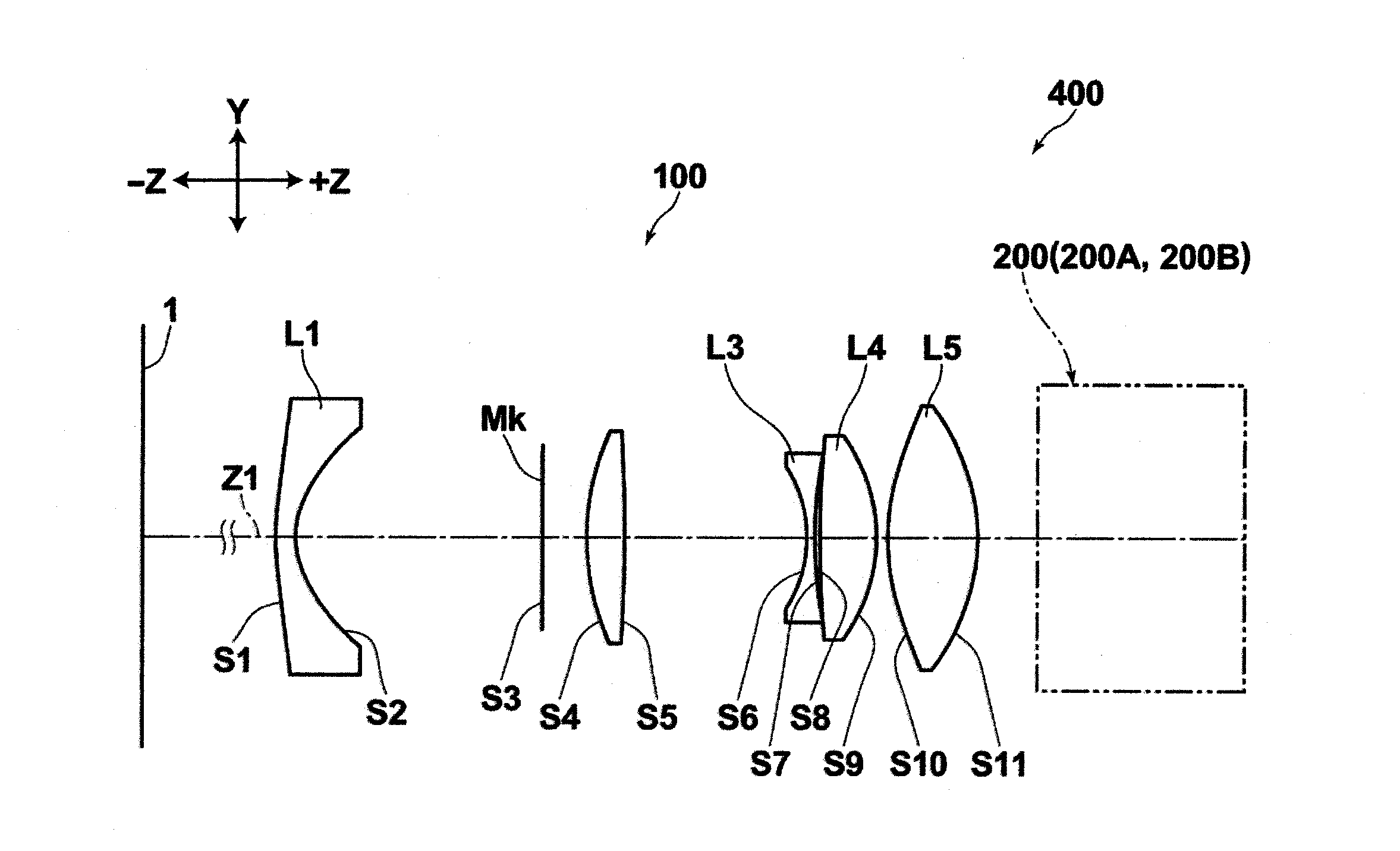
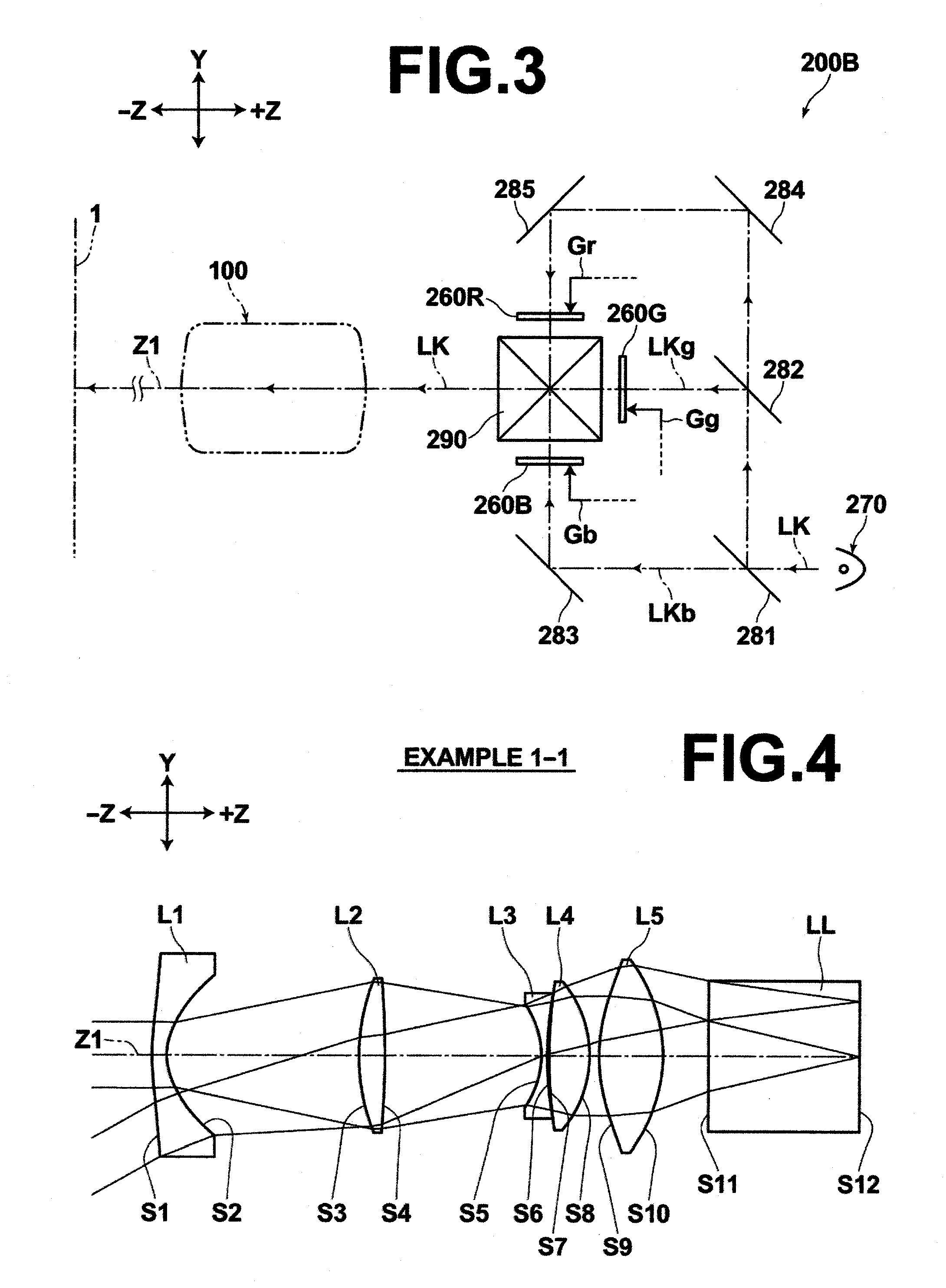
[0133]FIGS. 4 through 6 and FIGS. 10 through 13 are schematic cross sections illustrating the structure of the lenses for projection in Examples 1-1 through 1-3 and Comparative Examples 1 through 4, respectively.

[0134]In FIG. 4, which is a cross section illustrating a lens for projection in Example 1, optical paths of light passing through the lens for projection are also illustrated. FIG. 4 shows that the reduction side of the lens for projection in Example 1 is telecentric. In the other examples of the lens for projection, the re...


PUM


Abstract

A lens for projection substantially consists of a negative first-lens having a concave surface facing the reduction side, a positive second-lens having a convex surface facing the magnification side, a negative third-lens having a concave surface facing the magnification side, a positive fourth-lens having a convex surface facing the reduction side, and a positive fifth-lens, arranged in this order from the magnification side. Further, the following formulas (A) through (D) are satisfied:
1.2≦Bf/f≦2.5  (A);
−3.0≦f3F/f≦−0.8  (B);
1.4≦f5F/f5≦8.5  (C); and
1.0≦d12/f≦2.7  (D), where
    • Bf is a back focus,
    • f is the focal length of an entire lens system,
    • f3F is the focal length of a magnification-side surface of the third-lens,
    • f5F is the focal length of a magnification-side surface of the fifth-lens,
    • f5 is the focal length of the fifth-lens, and
    • d12 is an air space between the first-lens and the second-lens.

Description

BACKGROUND OF THE INVENTION[0001]1. Field of the Invention[0002]The present invention relates to a lens for projection and a projection-type display apparatus. In particular, the present invention relates to a lens for projection substantially consisting of five lenses and a projection-type display apparatus using the lens for projection.[0003]2. Description of the Related Art[0004]Projection-type display apparatuses (also called as projectors) rapidly spread in recent years. The projection-type display apparatuses project images represented by image data output from personal computers or the like onto screens. As such projectors, a projector that projects, through a lens for projection, light that has been output from a light source and modulated by a light valve onto a screen is known. As the light valve, a transmission-type liquid crystal device, a reflection-type liquid crystal device, a DMD (Digital Micromirror Device), and the like are known. In the DMD, micromirrors, the angl...

Claims


Application Information

Patent Timeline
Patent Type & Authority Applications(United States)
IPC IPC(8): G02B13/04G02B13/18
CPCG02B13/04
Inventor YAMAMOTO, CHIKARA
Owner FUJIFILM CORP
Why Eureka
Try Eureka