Photographing optical lens assembly, image capturing unit and electronic device

a technology of optical lens and image capturing unit, which is applied in the direction of optics, optical elements, instruments, etc., can solve the problem of difficult to obtain a balance for a conventional optical system

Active Publication Date: 2022-10-04
LARGAN PRECISION
View PDF28 Cites 4 Cited by
  • Summary
  • Abstract
  • Description
  • Claims
  • Application Information

AI Technical Summary

Benefits of technology

[0058]The sixth lens element can have positive refractive power. Therefore, it is favorable for reducing the total track length of the photographing optical lens assembly. The sixth lens element can have an object-side surface being convex in a paraxial region thereof and having at least one concave critical point in an off-axis region thereof. Therefore, it is favorable for correcting aberrations at the image periphery so as to increase relative illuminance on the image surface.
[0064]When a curvature radius of the object-side surface of the sixth lens element is R11, and a curvature radius of an image-side surface of the sixth lens element is R12, the following condition can be satisfied: (R11+R12) / (R11−R12)<0. Therefore, the surface shape of the sixth lens element is favorable for having a short back focal length and large image height in the photographing optical lens assembly. Moreover, the following condition can also be satisfied: −2.0<(R11+R12) / (R11−R12)<0.

Problems solved by technology

However, it is difficult for a conventional optical system to obtain a balance among the requirements such as high image quality, low sensitivity, a proper aperture size, miniaturization and a desirable field of view.

Method used


Image

  • Photographing optical lens assembly, image capturing unit and electronic device
  • Photographing optical lens assembly, image capturing unit and electronic device
  • Photographing optical lens assembly, image capturing unit and electronic device

Examples


1st embodiment

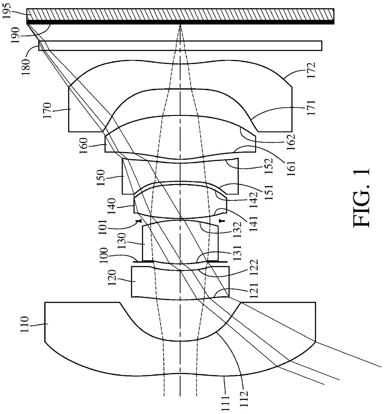
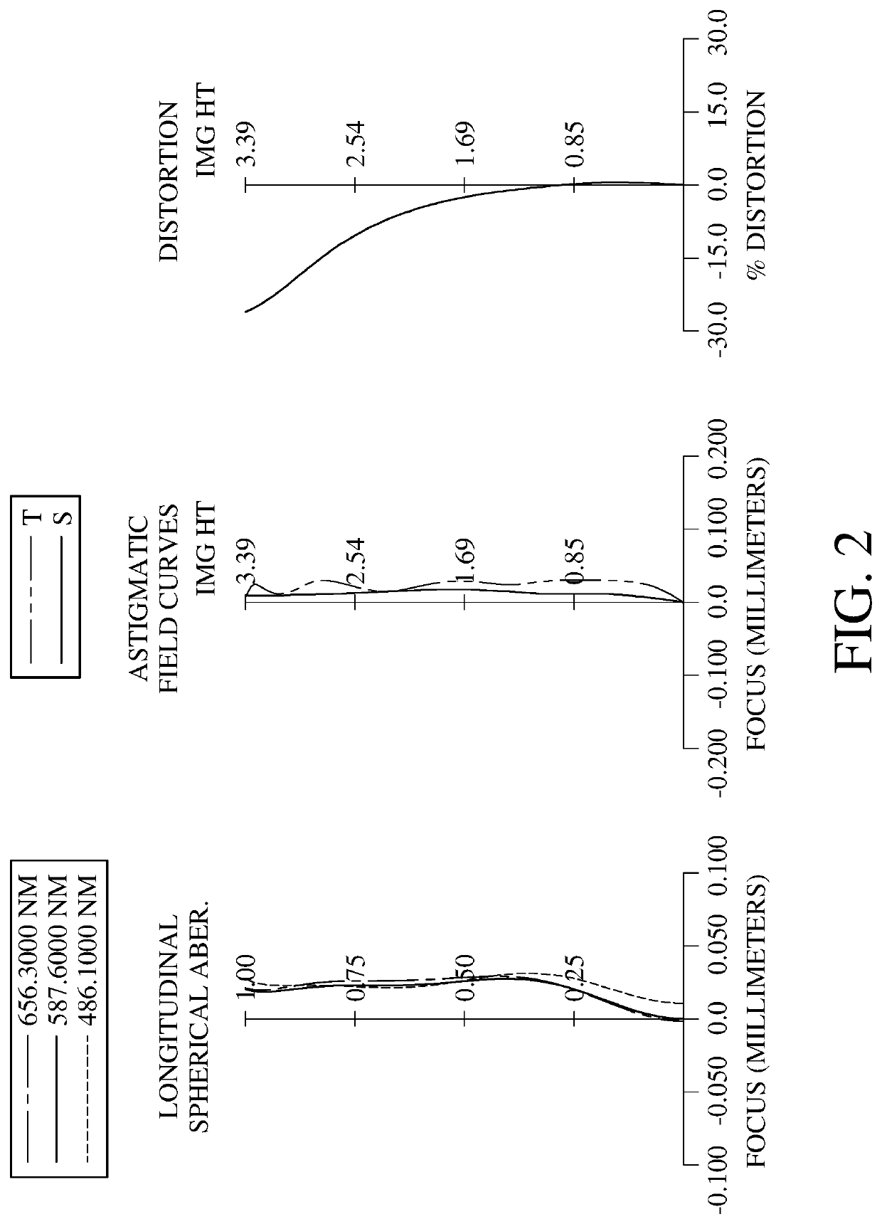
[0092]FIG. 1 is a schematic view of an image capturing unit according to the 1st embodiment of the present disclosure. FIG. 2 shows, in order from left to right, spherical aberration curves, astigmatic field curves and a distortion curve of the image capturing unit according to the 1st embodiment. In FIG. 1, the image capturing unit includes the photographing optical lens assembly (its reference numeral is omitted) of the present disclosure and an image sensor 195. The photographing optical lens assembly includes, in order from an object side to an image side along an optical path, a first lens element 110, a second lens element 120, an aperture stop 100, a third lens element 130, a stop 101, a fourth lens element 140, a fifth lens element 150, a sixth lens element 160, a seventh lens element 170, an IR-cut filter 180 and an image surface 190. The photographing optical lens assembly includes seven lens elements (110, 120, 130, 140, 150, 160 and 170) with no additional lens element d...

2nd embodiment

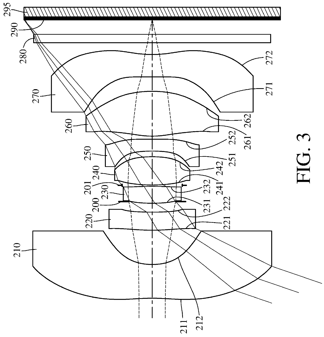
[0132]FIG. 3 is a schematic view of an image capturing unit according to the 2nd embodiment of the present disclosure. FIG. 4 shows, in order from left to right, spherical aberration curves, astigmatic field curves and a distortion curve of the image capturing unit according to the 2nd embodiment. In FIG. 3, the image capturing unit includes the photographing optical lens assembly (its reference numeral is omitted) of the present disclosure and an image sensor 295. The photographing optical lens assembly includes, in order from an object side to an image side along an optical path, a first lens element 210, a second lens element 220, an aperture stop 200, a third lens element 230, a stop 201, a fourth lens element 240, a fifth lens element 250, a sixth lens element 260, a seventh lens element 270, an IR-cut filter 280 and an image surface 290. The photographing optical lens assembly includes seven lens elements (210, 220, 230, 240, 250, 260 and 270) with no additional lens element d...

3rd embodiment

[0147]FIG. 5 is a schematic view of an image capturing unit according to the 3rd embodiment of the present disclosure. FIG. 6 shows, in order from left to right, spherical aberration curves, astigmatic field curves and a distortion curve of the image capturing unit according to the 3rd embodiment. In FIG. 5, the image capturing unit includes the photographing optical lens assembly (its reference numeral is omitted) of the present disclosure and an image sensor 395. The photographing optical lens assembly includes, in order from an object side to an image side along an optical path, a first lens element 310, a second lens element 320, an aperture stop 300, a third lens element 330, a stop 301, a fourth lens element 340, a fifth lens element 350, a sixth lens element 360, a seventh lens element 370, an IR-cut filter 380 and an image surface 390. The photographing optical lens assembly includes seven lens elements (310, 320, 330, 340, 350, 360 and 370) with no additional lens element d...


PUM


Abstract

A photographing optical lens assembly includes seven lens elements, which are, in order from an object side to an image side along an optical path: a first lens element, a second lens element, a third lens element, a fourth lens element, a fifth lens element, a sixth lens element and a seventh lens element. The first lens element has negative refractive power. The third lens element with positive refractive power has an image-side surface being convex in a paraxial region thereof. The fifth lens element has an object-side surface being concave in a paraxial region thereof. The sixth lens element has an object-side surface being convex in a paraxial region thereof. The seventh lens element has an image-side surface being concave in a paraxial region thereof and having at least one convex critical point in an off-axis region thereof.

Description

RELATED APPLICATIONS[0001]This application claims priority to Taiwan Application 108147636, filed on Dec. 25, 2019, which is incorporated by reference herein in its entirety.BACKGROUNDTechnical Field[0002]The present disclosure relates to a photographing optical lens assembly, an image capturing unit and an electronic device, more particularly to a photographing optical lens assembly and an image capturing unit applicable to an electronic device.Description of Related Art[0003]With the development of semiconductor manufacturing technology, the performance of image sensors has improved, and the pixel size thereof has been scaled down. Therefore, featuring high image quality becomes one of the indispensable features of an optical system nowadays.[0004]Furthermore, due to the rapid changes in technology, electronic devices equipped with optical systems are trending towards multi-functionality for various applications, and therefore the functionality requirements for the optical systems...

Claims


Application Information

Patent Timeline
Patent Type & Authority Patents(United States)
IPC IPC(8): G02B9/64G02B13/18G02B13/00
CPCG02B13/18G02B9/64G02B13/0045G02B13/06
Inventor WANG, KUO-JUILIN, CHENG-CHENCHEN, WEI-YU
Owner LARGAN PRECISION
Why Eureka
Try Eureka