Optical imaging lens
a technology of optical imaging and lens, applied in the field of optical elements, can solve the problems of worsening distortion aberration and other problems, and achieve the effects of reducing distortion aberration, reducing distortion aberration, and reducing distortion aberration
- Summary
- Abstract
- Description
- Claims
- Application Information
AI Technical Summary
Benefits of technology
Problems solved by technology
Method used
Image
Examples
first embodiment
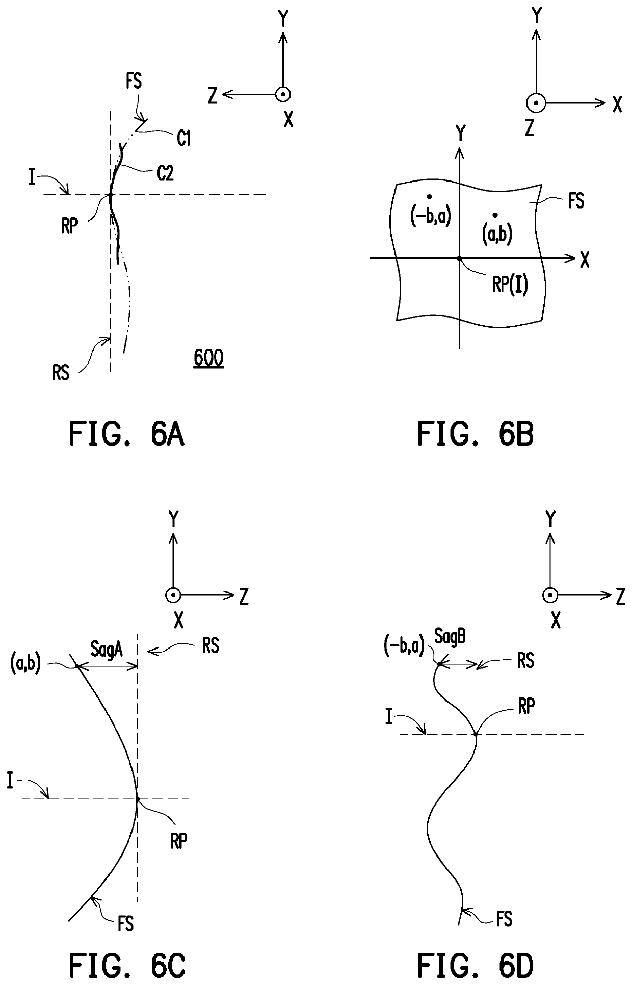
[0145]Coefficients of each term of the XmYn of the object-side surface 65 and the image-side surface 66 of the sixth lens element 6 in Formula (2) are shown in FIG. 10C and FIG. 10D. In FIG. 10C and FIG. 10D, a field number 65 corresponds to coefficients Cj of each term of the XmYn of the object-side surface 65 of the sixth lens element 6, and other fields may be deduced by analogy. In addition, in the present embodiment, coefficients Cj of the XmYn terms missing in FIG. 10C and FIG. 10D are zero. FIG. 10E shows the corresponding Sag values of the sixth lens element of the disclosure at the two selected coordinate values on the XY plane. Where the first coordinate value is, for example, X=3.000000, Y=1.000000, and the second coordinate value is, for example, X=−1.000000, Y=3.000000. The corresponding Sag values of the object-side surface 65 at the first and second coordinate values are −0.239578 and −0.218416, which are different from each other, and other fields may be deduced by a...
second embodiment
[0182]In addition, the relationships between important parameters of the optical imaging lens 10 in the second embodiment is shown in FIG. 47 and FIG. 48.
[0183]Longitudinal spherical aberrations of the second embodiment are shown in FIG. 12A, and imaging point deviations of off-axis rays at different heights are controlled within a range of ±0.018 mm. In two field curvature aberration diagrams of FIG. 12B and FIG. 12C, focal length variations of three representative wavelengths in an entire field of view fall within a range of ±0.05 mm. A distortion aberration diagram of FIG. 12D shows that distortion aberrations of the second embodiment are retained within a range of ±6%.
[0184]Based on the above, it can be seen that the HFOV in the second embodiment is greater than the HFOV in the first embodiment. Therefore, compared with the first embodiment, the second embodiment has a larger image receiving angle. In addition, the TTL of the second embodiment is shorter than the TTL of the firs...
third embodiment
[0188]In addition, the relationships between important parameters of the optical imaging lens 10 in the third embodiment is shown in FIG. 47 and FIG. 48.
[0189]Longitudinal spherical aberrations of the third embodiment are shown in FIG. 16A, and imaging point deviations of off-axis rays at different heights are controlled within a range of ±0.02 mm. In two field curvature aberration diagrams of FIG. 16B and FIG. 16C, focal length variations of three representative wavelengths in an entire field of view fall within a range of ±0.08 mm. A distortion aberration diagram of FIG. 16D shows that distortion aberrations of the third embodiment are retained within a range of ±6%.
[0190]FIG. 19A is a schematic diagram of an optical imaging lens according to a fourth embodiment of the disclosure. FIG. 19B is an enlarged radial cross-sectional view of the sixth lens element of FIG. 19A crossed by different planes. FIG. 19C is a schematic diagram of the appearance of the sixth lens element of FIG. ...
PUM
 Abstract
Description
Claims
Application Information
 - R&D
- Intellectual Property
- Life Sciences
- Materials
- Tech Scout
- Unparalleled Data Quality
- Higher Quality Content
- 60% Fewer Hallucinations
Browse by: Latest US Patents, China's latest patents, Technical Efficacy Thesaurus, Application Domain, Technology Topic, Popular Technical Reports.
© 2025 PatSnap. All rights reserved.Legal|Privacy policy|Modern Slavery Act Transparency Statement|Sitemap|About US| Contact US: help@patsnap.com


