

Lens Assembly
a technology of lens assembly and lens body, which is applied in the field of lens assembly, can solve the problems that the known lens assembly cannot meet such requirements
- Summary
- Abstract
- Description
- Claims
- Application Information
AI Technical Summary
Benefits of technology
Problems solved by technology
Method used
Image

Examples
first embodiment
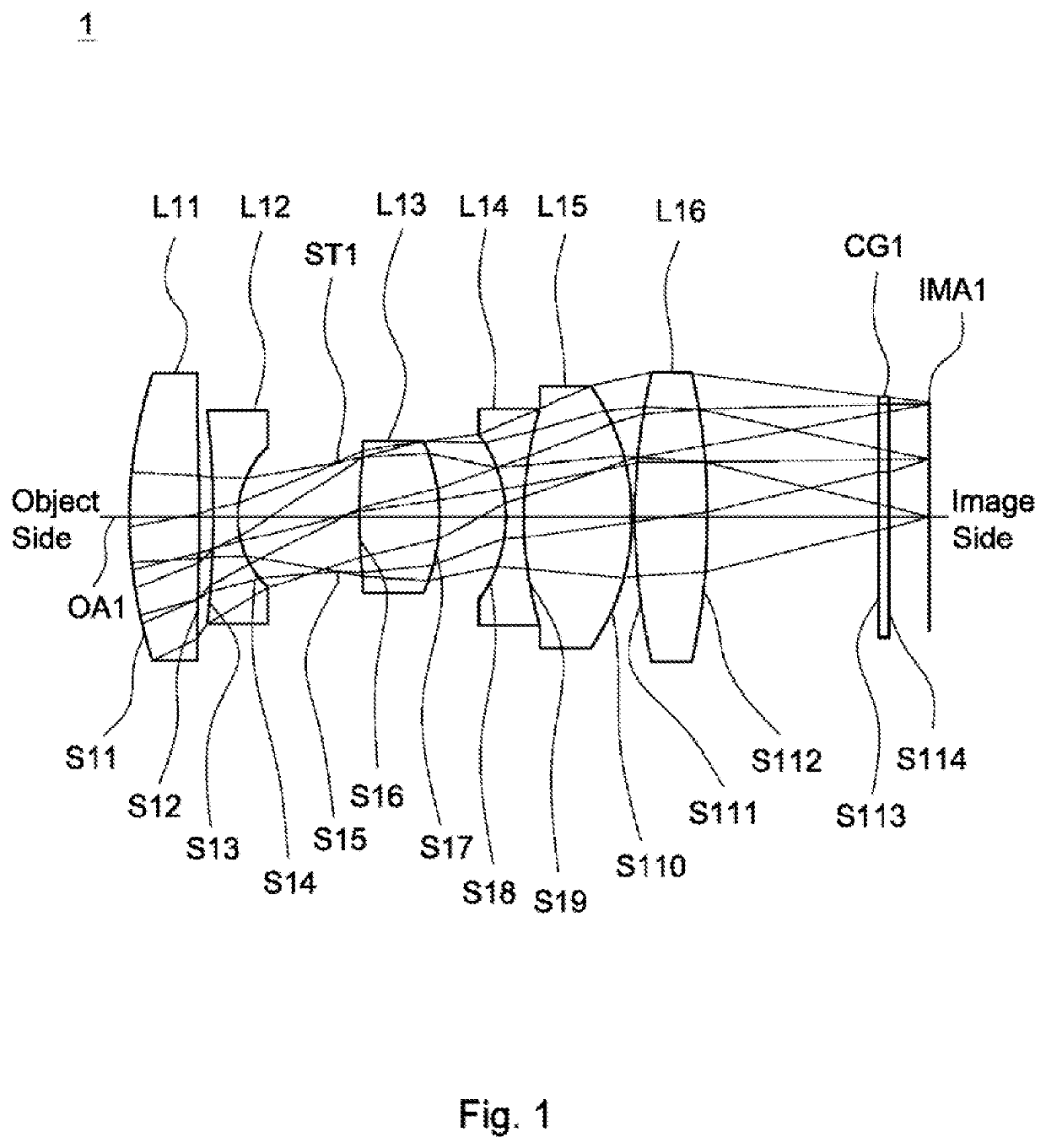
[0054]A detailed description of a lens assembly in accordance with the invention is as follows. Referring to FIG. 1, the lens assembly 1 includes a first lens L11, a second lens L12, a stop ST1, a third lens L13, a fourth lens L14, a fifth lens L15, a sixth lens L16, and a cover glass CG1, all of which are arranged in order from an object side to an image side along an optical axis OA1. In operation, the light from the object side is imaged on an image plane IMA1.
[0055]According to paragraphs [0030]-[0037], wherein: the first lens L11 is a biconvex lens, wherein the image side surface S12 is a convex surface; the second lens L12 is a biconcave lens, wherein the object side surface S13 is a concave surface; both of the object side surface S19 and image side surface S110 of the fifth lens L15 are spherical surfaces; the sixth lens L16 is a biconvex lens, wherein the object side surface S111 is a convex surface, and both of the object side surface S111 and image side surface S112 are a...
second embodiment
[0067]In the second embodiment, the conic constant k and the aspheric coefficients A, B, C, D, E, F, G of each aspheric lens are shown in Table 5.
TABLE 5SurfaceABCNumberkEFGDS211 4.42581.5292E−05−5.3467E−085.5819E−09−1.7872E−10000S212−3.83469.8423E−05−3.4255E−071.5865E−08−2.7897E−10000
[0068]Table 6 shows the parameters and condition values for conditions (1)-(7) in accordance with the second embodiment of the invention. It can be seen from Table 5 that the lens assembly 2 of the second embodiment satisfies the conditions (1)-(7).
TABLE 6BFL12.13 mmf45−54.01 mmTTL / f4.02TTL / BFL3.30(R11 + R12) / −0.68| f45 / f |5.43(R11 − R12)f4 / f5−0.62Vd5 − Vd425.80R32 / R31−0.40
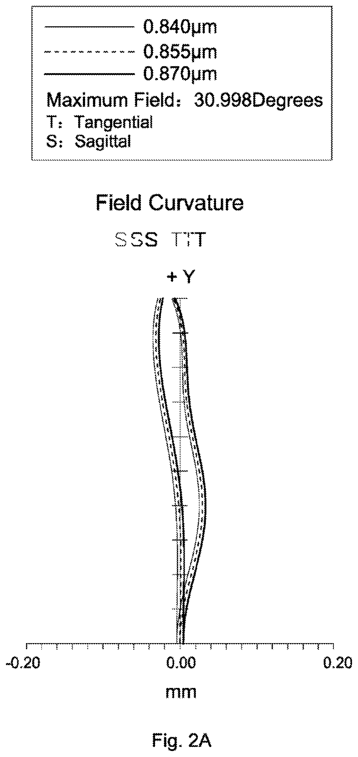
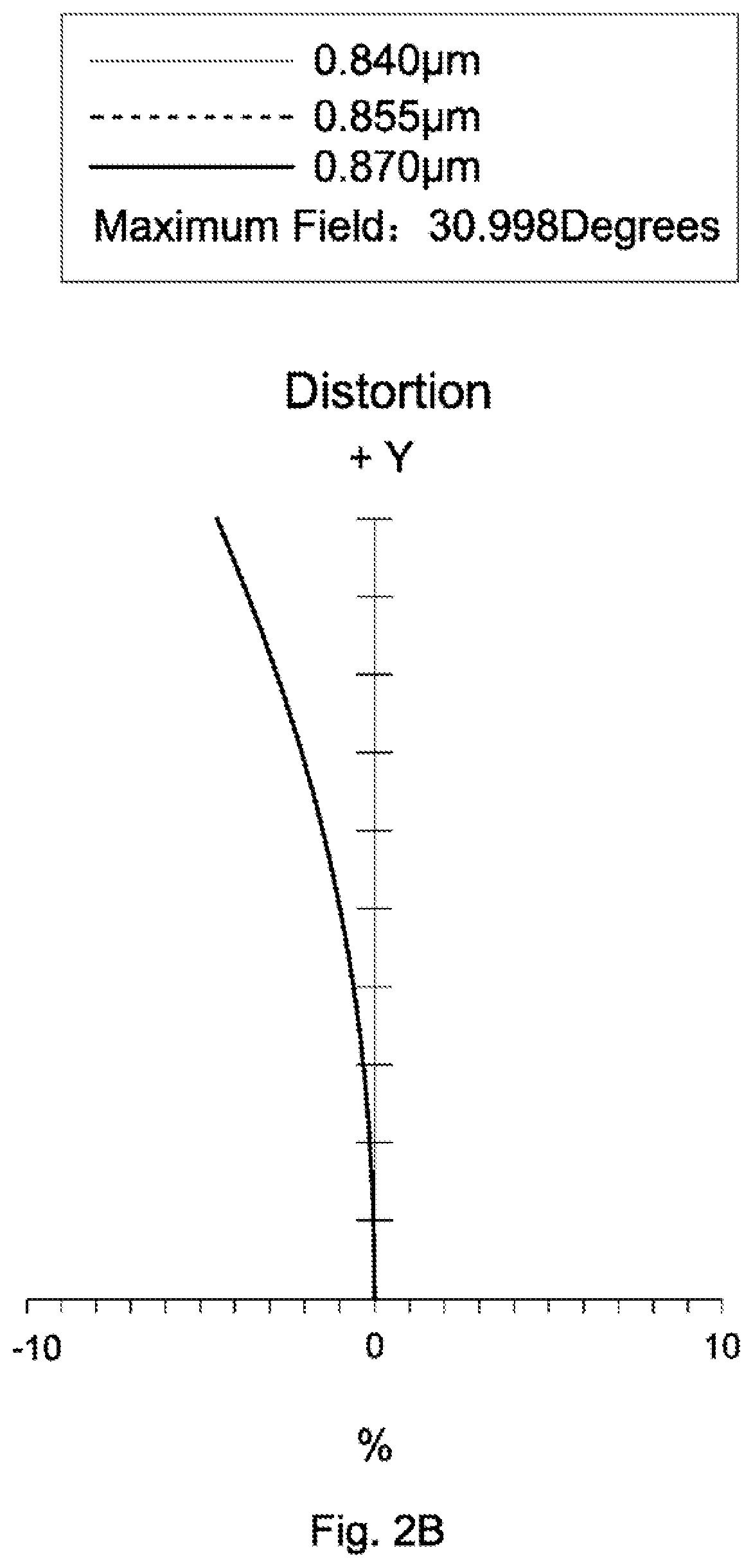
[0069]In addition, the lens assembly 2 of the second embodiment can meet the requirements of optical performance, wherein the field curvature diagram, the distortion diagram, the spot diagram, and the modulation transfer function diagram are similar to those of the lens assembly 1 of the first embodiment, so that those figures are om...
third embodiment
[0075]In the third embodiment, the conic constant k and the aspheric coefficients A, B, C, D, E, F, G of each aspheric lens are shown in Table 8.
TABLE 8SurfaceABCNumberkEFGDS311−2.2584−4.5167E−05 1.6797E−06−5.8487E−08 1.2506E−09−1.7826E−11 1.9229E−13−1.0650E−15S312−1.6996 4.4510E−05−2.8055E−07 3.2515E−08−1.0479E−09 1.0423E−11 8.8425E−14−1.5030E−15
[0076]Table 9 shows the parameters and condition values for conditions (1)-(7) in accordance with the third embodiment of the invention. It can be seen from Table 9 that the lens assembly 3 of the third embodiment satisfies the conditions (1)-(7).
TABLE 9BFL11.58 mmf45−51.34 mmTTL / f4.20TTL / BFL3.45(R11 + R12) / −0.69| f45 / f |5.39(R11 − R12)f4 / f5−0.62Vd5 − Vd425.80R32 / R31−0.32
[0077]In addition, the lens assembly 3 of the third embodiment can meet the requirements of optical performance as seen in FIGS. 5A-5D. It can be seen from FIG. 5A that the field curvature of tangential direction and sagittal direction in the lens assembly 3 of the third em...
PUM
 Abstract
Description
Claims
Application Information