Chair with seat depth adjustment and back support

a seat depth adjustment and back support technology, applied in the field of chairs with seat depth adjustment and back support, office chairs, can solve the problems of increasing the complexity and cost of assembling and manufacturing office chairs, increasing the cost of manufacturing office chairs, and increasing the cost of movable seats

Active Publication Date: 2015-04-23
OFFICE MASTER INC
View PDF17 Cites 26 Cited by
  • Summary
  • Abstract
  • Description
  • Claims
  • Application Information

AI Technical Summary

Benefits of technology

[0008]When a user exerts a force against the seat back, the entire swing arm pivots about its connection to the seat pan. The pivoting movement of the swing arm causes the chair back to recline. The reclining movement of the chair back causes the roller to travel along the curved support face to provide adequate support for the chair back. As the chair back reclines and moves relative to the stationary support bar, the movement of the swing arm along the stationary support bar causes the seat pan to move forward along a longitudinal axis relative to the stationary seat base. A bias spring is positioned between the stationary seat base and the seat pan to restrict the movement of the seat pan as described. In this manner, the bias spring provides a bias force to hold the chair back and chair seat in a retracted, upright position.

Problems solved by technology

Although office chairs exist that allow the chair back to pivot and the chair seat to move forward, most of these office chairs include complex mechanical linkages to couple the movement of the chair back and the chair seat.
The complex arrangement between the chair back and the chair seat increases the cost of manufacturing the office chair and increases the cost and time to assemble such a chair.
Once again, many of these currently available chairs include complex mechanical components that increase the complexity and cost of assembling and manufacturing the office chair.

Method used


Image

  • Chair with seat depth adjustment and back support
  • Chair with seat depth adjustment and back support
  • Chair with seat depth adjustment and back support

Examples


Embodiment Construction

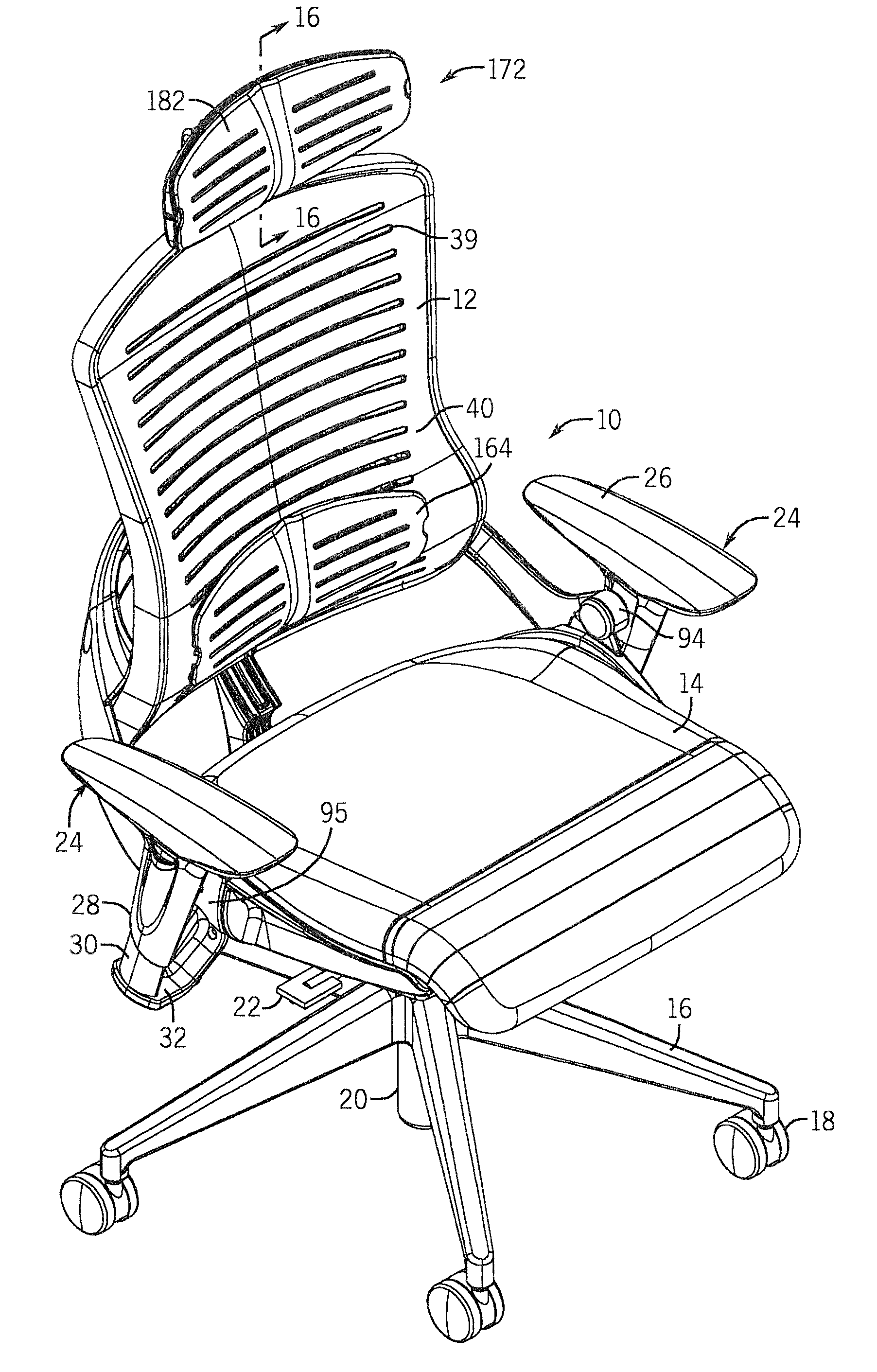
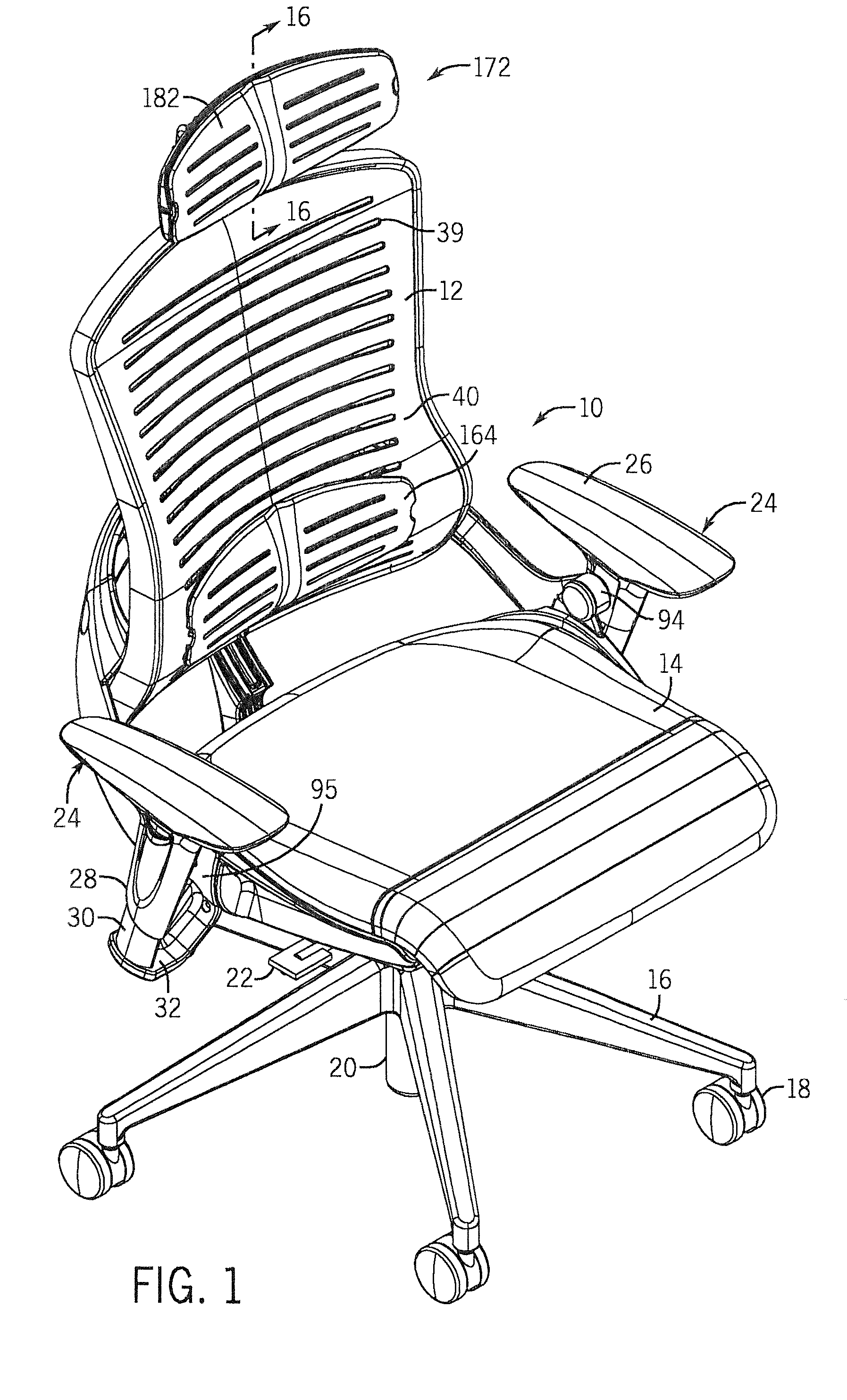
[0033]FIG. 1 generally illustrates an office chair 10 constructed in accordance with one embodiment of the disclosure. The office chair 10 generally includes a chair back 12 and a chair seat 14 supported about a pedestal base 16. The pedestal base 16 includes a plurality of caster wheels 18 that allow the base to move the chair as is well known. The pedestal base 16 includes a gas assisted lift mechanism 20 controlled by lever 22 in a conventional manner.

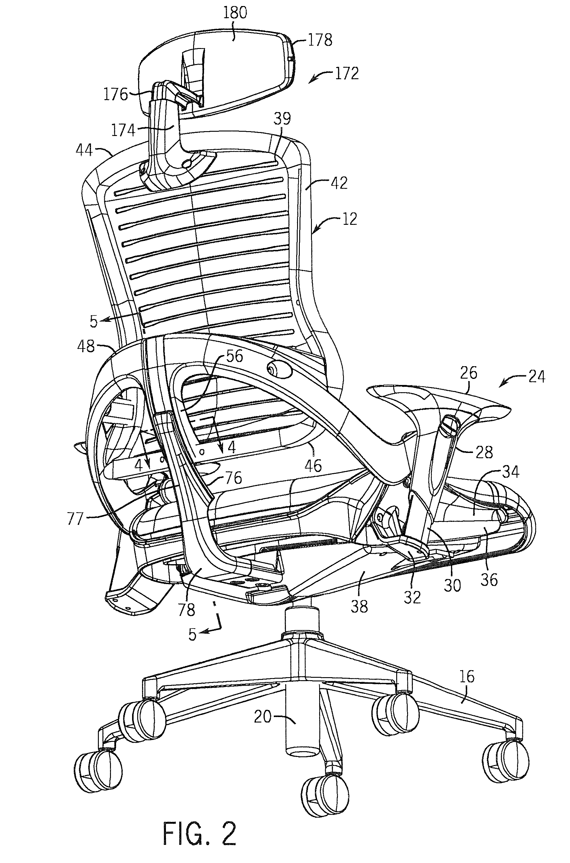
[0034]The office chair 10 includes a pair of arms 24 each having a padded upper portion 26 mounted to a lower adjustment tube 28. The lower adjustment tube 28 is movable along a stationary post 30. The stationary post 30, in turn, is supported by an attachment bracket 32. The attachment bracket 32 is securely attached to a sidewall 34 of a seat pan 36, as is best shown in FIG. 2. The seat pan 36 is a plastic, molded component that is movable along a longitudinal axis relative to seat base 38 in a manner to be described in much great...


PUM


Abstract

An office chair including a linking mechanism between a movable chair seat and a pivotable chair back. The mounting arrangement between the chair back and the chair seat includes swing arm assembly that is pivotally connected to the chair seat. When the chair seat moves forward, the swing arm assembly moves with the chair seat and causes the chair back to pivot and move relative to a stationary support arm. The stationary support arm includes a curved support face that moves within a movement, slot formed on the swing arm assembly. The movement slot includes a roller that helps guide relative movement between the two components. The chair seat includes a thigh support portion that allows the user to adjust the seat depth as desired.

Description

BACKGROUND OF THE INVENTION[0001]The present disclosure generally relates to an office chair. More specifically, the present disclosure relates to an office chair that allows for pivoting movement of the chair back and forward movement of the chair seat during reclining by the user.[0002]Presently, many different types of office chairs exist that allow the chair back to recline and the chair seat to move forward as the chair back reclines. The dual movement of the chair seat and the chair back enhances comfort for the user.[0003]Although office chairs exist that allow the chair back to pivot and the chair seat to move forward, most of these office chairs include complex mechanical linkages to couple the movement of the chair back and the chair seat. The complex arrangement between the chair back and the chair seat increases the cost of manufacturing the office chair and increases the cost and time to assemble such a chair.[0004]Many currently available office chairs also include var...

Claims


Application Information

Patent Timeline
Patent Type & Authority Applications(United States)
IPC IPC(8): A47C1/032A47C7/38A47C7/54A47C1/034
CPCA47C1/03294A47C7/54A47C7/38A47C1/034A47C1/023A47C7/46A47C1/031A47C7/425B60N2/0284
Inventor ROMERO, FRANCISCO
Owner OFFICE MASTER INC
Why Eureka
Try Eureka