Treadmill with workstation

a workstation and treadmill technology, applied in the field of treadmills, can solve the problems of reducing affecting the safety of users, and the treadmill disclosed above cannot be used for running and workstations, so as to achieve the effect of not jeopardizing the exercise feeling of the user and being convenient to opera

Active Publication Date: 2014-05-27
HSIEH PAUL
View PDF14 Cites 43 Cited by
  • Summary
  • Abstract
  • Description
  • Claims
  • Application Information

AI Technical Summary

Benefits of technology

[0011]Another advantage of the invention is to provide a treadmill comprising a tread utility assembly, which is securely yet adjustably mounted on a tread assembly so as to allow the tread utility assembly to be used as a wide variety of equipments and platforms, and to suit a wide variety of users having different heights and exercising parameters.
[0012]Another advantage of the invention is to provide a treadmill comprising a tread utility assembly which is outwardly extended from a control unit so that a user is able to easily operate on the control unit while allowing other activities to be carried out by the tread utility assembly. More importantly, this construction does not jeopardize the feeling of exercise on the part of the user because the user will mainly be concerned with controlling the exercising parameters of the treadmill. In other words, exercise activities are given first priority when the user is using the treadmill of the present invention.
[0013]Another advantage of the invention is to provide a treadmill comprising a plurality of handle bars extended from the control unit for providing adequate support to the user of the present invention. This is in stark contrast with conventional treadmill described above because the workstation was the sole support given to the user.
[0014]Another advantage of the invention is to provide a treadmill comprising a tread utility assembly which is arranged to form a triangular support structure for providing secure yet movable support to a utility member.
[0015]Additional advantages and features of the invention will become apparent from the description which follows, and may be realized by means of the instrumentalities and combinations particular point out in the appended claims.
[0016]According to the present invention, the foregoing and other objects and advantages are attained by providing a treadmill, comprising:

Problems solved by technology

There are several disadvantages in association with this conventional treadmill.
First, the treadmill disclosed above can only be used for running and for workstation.
This arrangement substantially reduces the feeling of exercise on the part of the user.
The second disadvantage relates to safety issues.
Since the user does not have the feeling of exercise, he or she may over-concentrate on his or her work and therefore forgets the fact that the tread assembly is still running.
This is extremely dangerous because the user may concentrate in reading or typing a document or email without being aware that he or she needs to keep up his or speed to run.
When the user slows down his or her running speed, he or she may fall from the tread assembly.
Third, the conventional treadmill described above does not allow the user to perform something else while exercising.
In other words, the user may purchase the conventional treadmill with a view to perform some work but later finds that the workstation cannot be used to perform something else.
The problem with this construction is that when the user is running on the tread assembly, the entire treadmill will shake as a result.
The workstation will not be securely supported by the supporting shafts alone and the electronic equipments placed on the workstation, such as computers, may be affected or even damaged by the impact generated by the vibrations.
Fifth, the workstation supported on the treadmill is generally not movable.
This means that the user will not be able to adjust the angle of inclination of the workstation with respect to the supporting shafts.
This limitation brings great inconvenience to the user of the conventional treadmill.

Method used


Image

  • Treadmill with workstation
  • Treadmill with workstation
  • Treadmill with workstation

Examples


Embodiment Construction

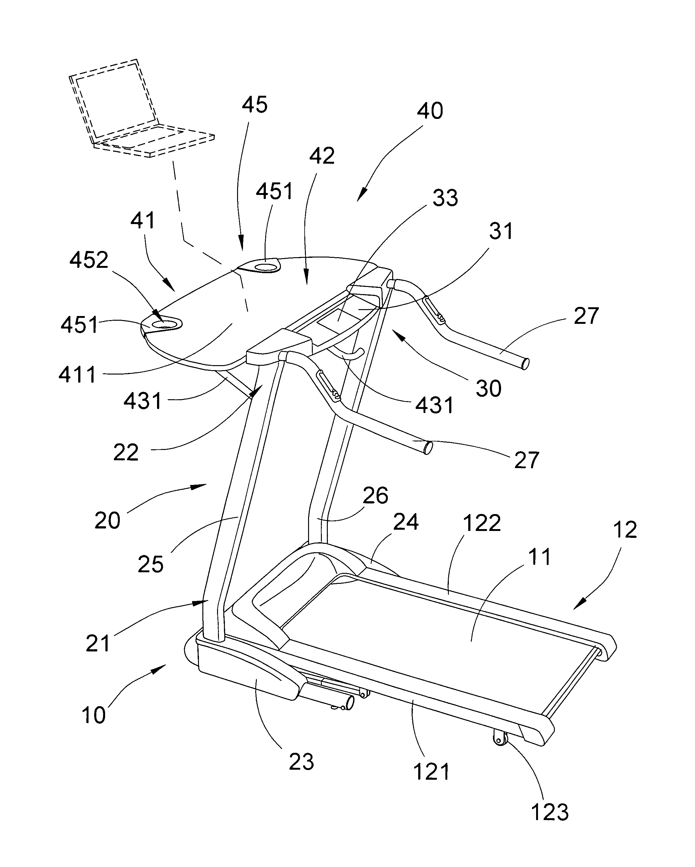
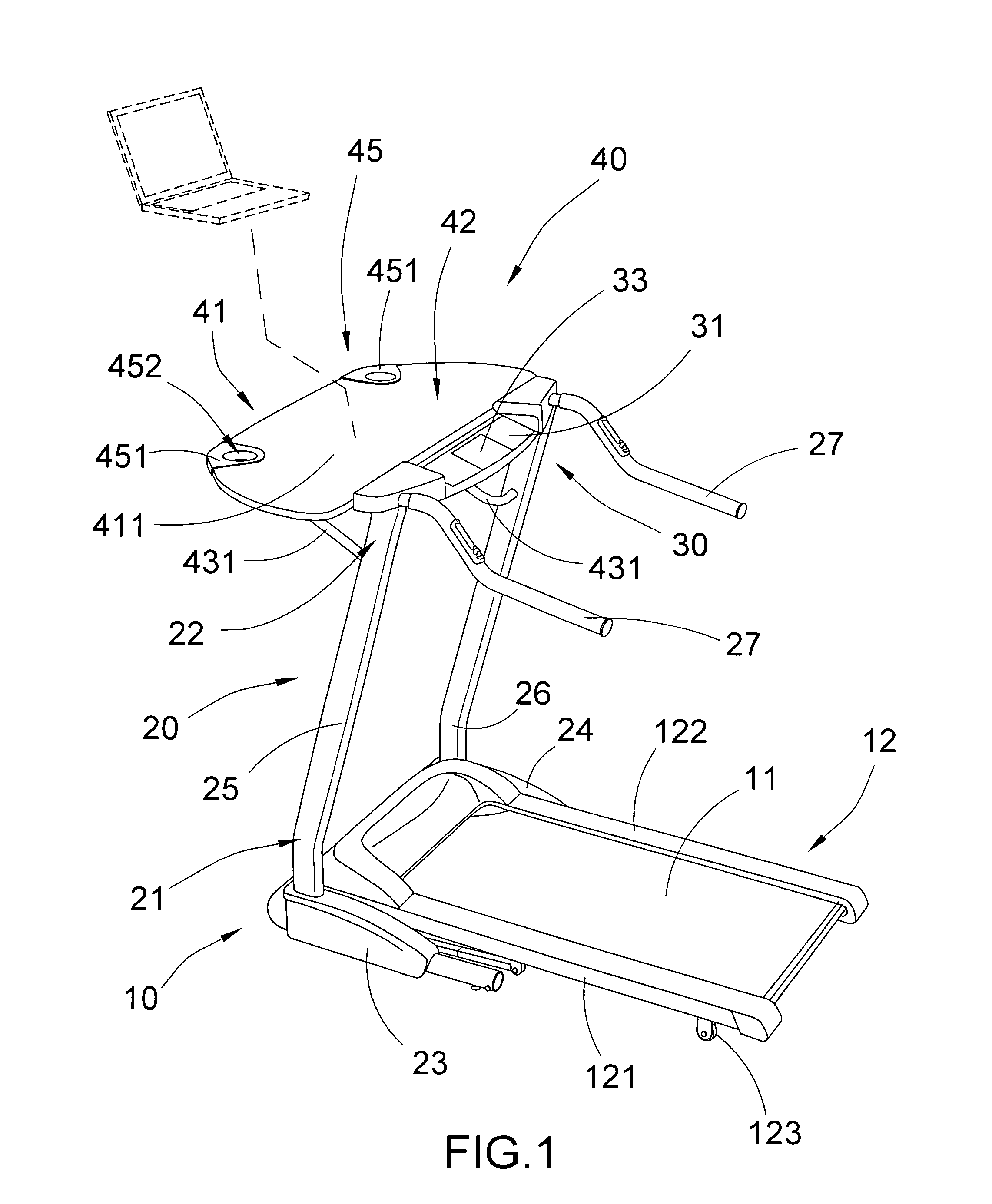
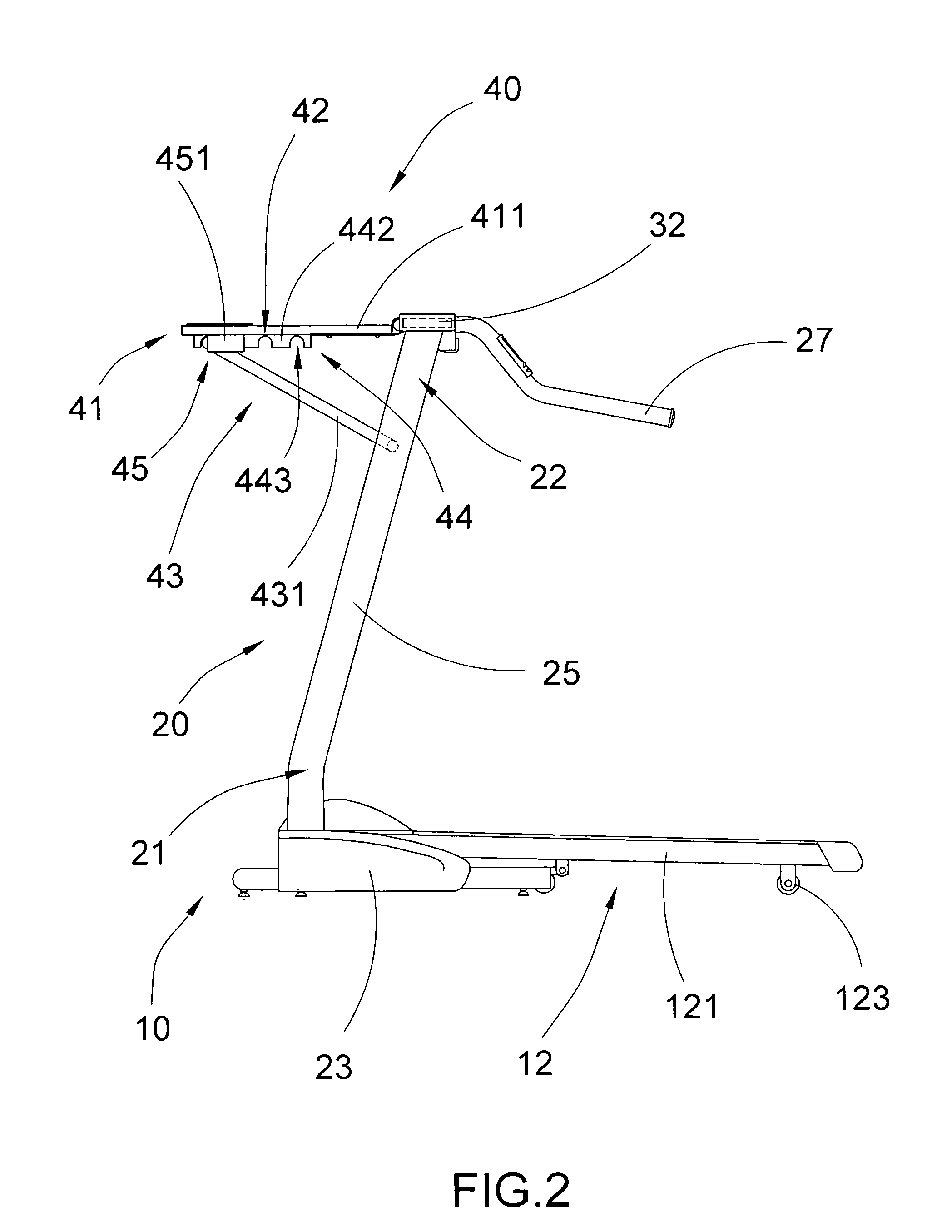
[0030]Referring to FIG. 1 to FIG. 2, FIG. 3A to FIG. 3B, FIG. 4, and FIG. 5 of the drawings, a treadmill according to a preferred embodiment of the present invention is illustrated, in which the treadmill comprises a tread assembly 10, a supporting frame 20, a control unit 30, and a tread utility assembly 40. The tread assembly 10 comprises a movable runner tread 11 for a user to run thereon.

[0031]The supporting frame 20 has a lower end portion 21 connected to a front end portion of the tread assembly 10, and an upper end portion 22 extended from the lower end portion 21 at a predetermined evaluation above the tread assembly 10.

[0032]The control unit 30 is mounted at the upper end portion 22 of the supporting frame 20 for controlling an operation of the tread assembly 10.

[0033]The tread utility assembly 40 comprises a utility member 41 outwardly and movably extended from the control unit 30 to form a utility platform 42 which has a predetermined angle of inclination with respect to ...


PUM


Abstract

A treadmill includes a tread assembly, a supporting frame, a control unit and a tread utility assembly. The supporting frame has a lower end portion connected to a front end portion of the tread assembly, and an upper end portion extended from the lower end portion at a predetermined evaluation. The control unit is mounted at the upper end portion of the supporting frame for controlling an operation of the tread assembly. The tread utility assembly includes a utility member frontwardly and movably extended from the control unit to form a utility platform which has a predetermined angle of inclination with respect to the control unit, wherein a user is allowed to simultaneously operate the control unit and run on the tread assembly, and accomplish a predetermined task on the utility platform in a convenient and safe manner.

Description

BACKGROUND OF THE PRESENT INVENTION[0001]1. Field of Invention[0002]The present invention relates to a treadmill, and more particularly to a treadmill comprising a tread utility assembly which is capable of facilitating accomplishment of a wide variety of tasks when a user is exercising on the treadmill.[0003]2. Description of Related Arts[0004]A conventional treadmill, such as that disclosed in U.S. Pat. No. 7,892,148 usually comprises a tread assembly, a support structure extended from the tread assembly, a tabletop member mounted to a distal top end of the support structure, a handle member supported by the table top member adjacent the front edge of the table top member, and a control assembly including at least one input button supported by at least one of the table top member and the handle member. The table top member includes an undersurface and the control assembly is mounted to the undersurface of the table top member adjacent the front edge of the table top member and bel...

Claims


Application Information

Patent Timeline
Patent Type & Authority Patents(United States)
IPC IPC(8): A63B22/02
CPCA63B2225/08A63B2225/682A63B22/02A47B83/00A63B2225/685
Inventor HSIEH, PAUL
Owner HSIEH PAUL
Why Eureka
Try Eureka