Stretch film dispenser with lifting device

Active Publication Date: 2019-11-19
YU CHEN HSIU MAN
20 Cites 6 Cited by

AI-Extracted Technical Summary

Problems solved by technology

However, although the stretch film dispenser is convenient for the user to pack the article, the length of the rod cannot be adjusted.
For the article that is located at a higher or lower position, it is inconvenient for the user to apply a force to pack the article, a...

Benefits of technology

[0008]The lifting device of the stretch film dispenser provided by the present invention controls the telescopic rod to extend up and down through the first operating unit and the second operating unit, so that the stretch film dispenser is suitable for articles of different heights. The telesc...

Abstract

A stretch film dispenser with a lifting device is disclosed. The lifting device includes a first operating unit. The first operating unit has a first through hole. The first through hole is provided with a first fixing member. The first operating unit further has a first opening. The first opening is provided with a first control member. The first operating unit is connected with an accommodating unit. The accommodating unit includes a telescopic rod therein. An outer peripheral wall of the telescopic rod is formed with a plurality of spaced first positioning holes corresponding to the first fixing member. The first fixing member is engaged in one of the plurality of first positioning holes for positioning the telescopic rod. Thereby, the telescopic adjustment of the telescopic rod is controlled by the first operating unit for articles of different heights, and the packing process is more smooth and convenient.

Application Domain

Wrapping material feeding apparatusFunction indicators +1

Technology Topic

EngineeringElectrical and Electronics engineering

Image

  • Stretch film dispenser with lifting device
  • Stretch film dispenser with lifting device
  • Stretch film dispenser with lifting device

Examples

  • Experimental program(1)

Example

[0020]Embodiments of the present invention will now be described, by way of example only, with reference to the accompanying drawings.
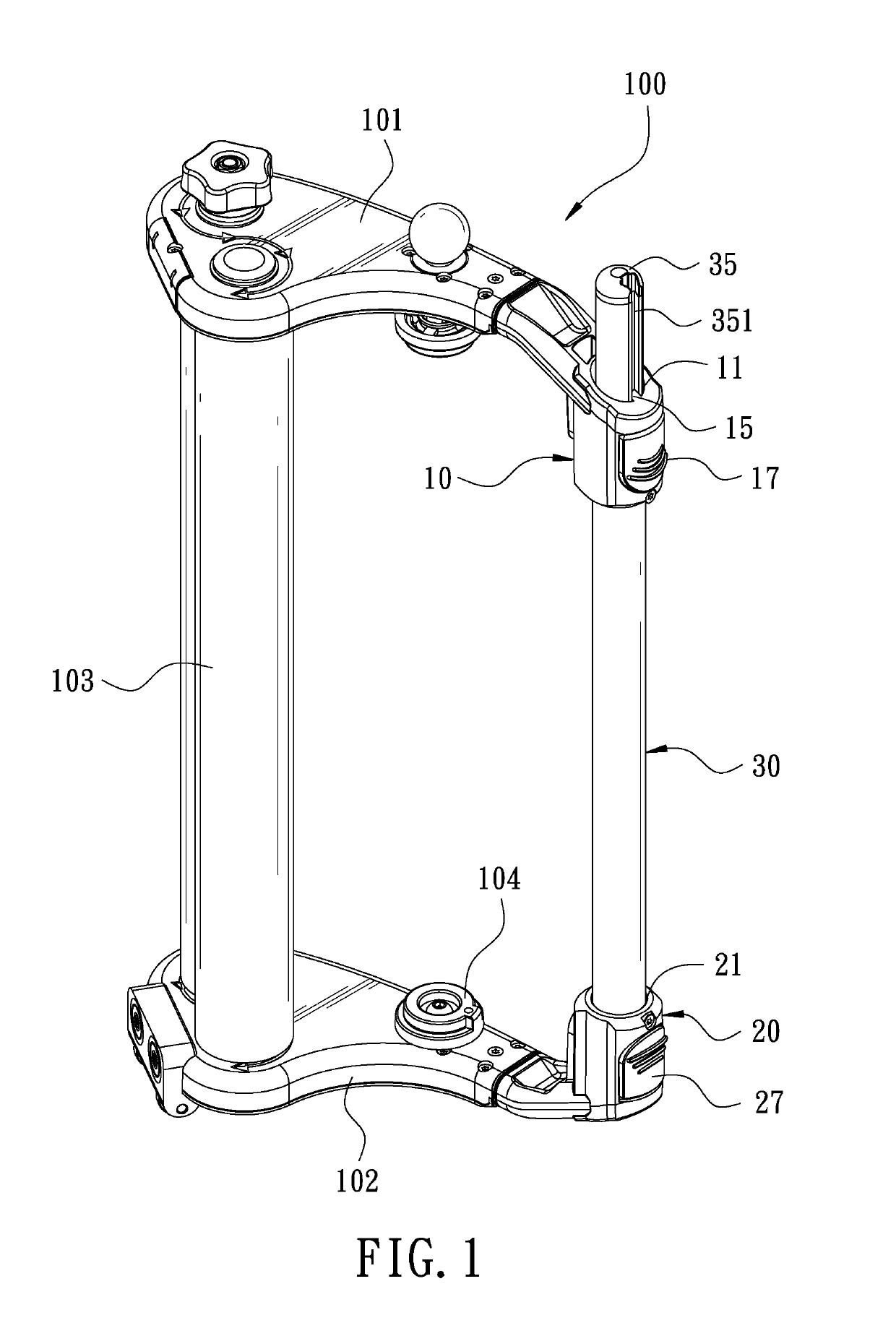
[0021]FIG. 1 is a perspective view in accordance with a preferred embodiment of the present invention. The present invention discloses a stretch film dispenser with a lifting device. The lifting device is mounted to a stretch film dispenser 100. The stretch film dispenser 100 comprises a first seat 101 and a second seat 102. The lifting device is disposed between the first seat 101 and the second seat 102. The stretch film dispenser 100 further comprises a roller assembly 103 and a film mounting unit 104.
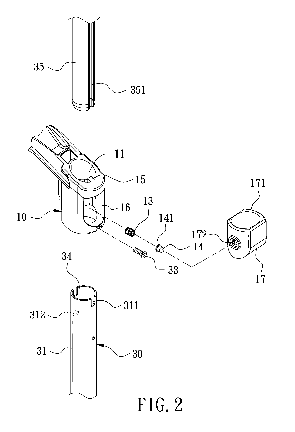
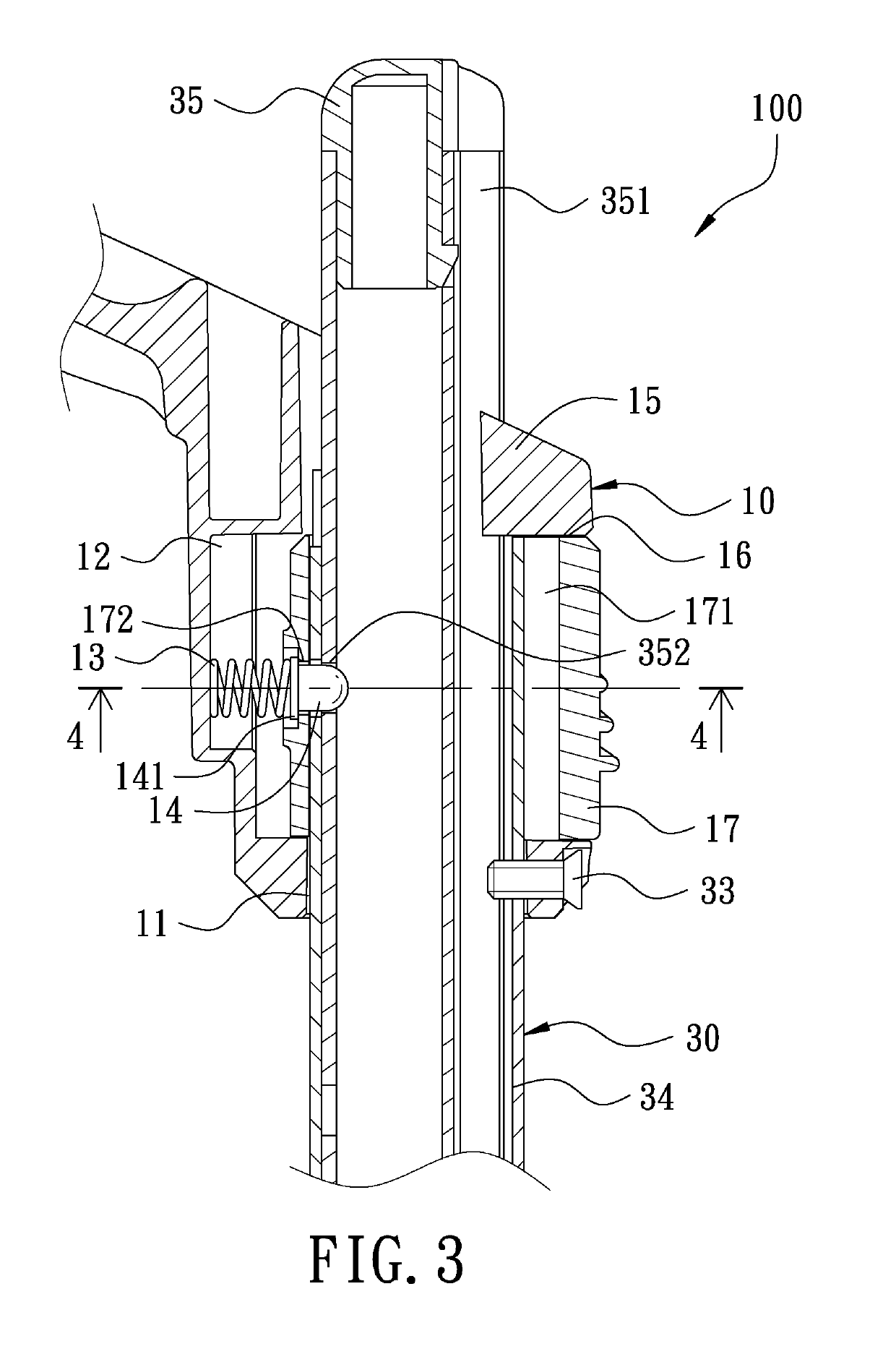
[0022]Referring to FIG. 2 and FIG. 3, a first operating unit 10 is connected to one end of the first seat 101. The first operating unit 10 is provided with a first through hole 11. A peripheral wall of the first through hole 11 is formed with a first accommodating recess 12. The first accommodating recess 12 is provided with a first elastic member 13. An elastic end of the first elastic member 13 leans against a first fixing member 14. An immovable end of the first fixing member 14 is formed with an annular first flange 141. The first flange 141 is biased by the first elastic member 13. A first positioning block 15 protrudes from the peripheral wall of the first through hole 11. An outer peripheral wall of the first operating unit 10 is formed with a first opening 16 corresponding in position to the first accommodating recess 12. The first opening 16 is in communication with the first through hole 11. The first opening 16 of the first operating unit 10 is provided with a first control member 17. The first control member 17 has an elliptical first perforation 171. The central axis of the first perforation 171 is parallel to the central axis of the first through hole 11. As shown in FIG. 4, the first control member 17 has a first limiting hole 172 corresponding to the first fixing member 14. The first flange 141 of the first fixing member 14 is blocked by the first limiting hole 172 of the first control member 17. A free end of the first fixing member 14 is inserted into the first perforation 171 of the first control member 17.
[0023]Referring to FIG. 5 and FIG. 6, a second operating unit 20 is connected to one end of the second seat 102. The second operating unit 20 is provided with a second through hole 21. A peripheral wall of the second through hole 21 is formed with a second accommodating recess 22. The second accommodating recess 22 is provided with a second elastic member 23. An elastic end of the second elastic member 23 leans against a second fixing member 24. An immovable end of the second fixing member 24 is formed with an annular second flange 241. The second flange 241 is biased by the second elastic member 23. A second positioning block 25 protrudes from the peripheral wall of the second through hole 21. The first positioning block 15 is parallel to the second positioning block 25. An outer peripheral wall of the second operating unit 20 is formed with a second opening 26 corresponding in position to the second accommodating recess 22. The second opening 26 is in communication with the second through hole 21. The second opening 26 of the second operating unit 20 is provided with a second control member 27. The second control member 27 has an elliptical second perforation 271. The central axis of the second perforation 271 is parallel to the central axis of the second through hole 21. As shown in FIG. 11, the second control member 27 has a second limiting hole 272 corresponding to the second fixing member 24. The second flange 241 of the second fixing member 24 is blocked by the second limiting hole 272 of the second control member 27. A free end of the second fixing member 24 is inserted into the second perforation 271 of the second control member 27.
[0024]An accommodating unit 30 has a first end 31 disposed in the first through hole 11 of the first operating unit 10 and a second end 32 disposed in the second through hole 21 of the second operating unit 20. Referring to FIG. 2, FIG. 3 and FIG. 4, the first end 31 of the accommodating unit 30 is formed with a first engaging notch 311 corresponding to the first positioning block 15 of the first through hole 11. The first engaging notch 311 is engaged with the first positioning block 15. The accommodating unit 30 is locked by a screw 33. The first end 31 has a first aperture 312 corresponding to the first limiting hole 172 of the first control member 17. The free end of the first fixing member 14 passes through the first aperture 312. Please refer to FIG. 5, FIG. 6, FIG. 10 and FIG. 11, the second end 32 of the accommodating unit 30 is formed with a second engaging notch 321 corresponding to the second positioning block 25 of the second through hole 21. The second engaging notch 321 is engaged with the second positioning block 25. The accommodating unit 30 is locked by a screw 33. In the embodiment, the accommodating unit 30 is a hollow tube. The accommodating unit 30 has a receiving hole 34 therein. The receiving hole 34 is provided with a telescopic rod 35. The length of the telescopic rod 35 is greater than the length of the accommodating unit 30. An outer peripheral wall of the telescopic rod 35 is formed with a groove 351 corresponding to the first positioning block 15 and the second positioning block 25 for limiting the telescopic rod 35. Please refer to FIG. 7. The telescopic rod 35 defines a first axis a and a second axis b. The first axis a and the second axis b are spaced apart from each other. The telescopic rod 35 is formed with a plurality of first positioning holes 352 that are arranged along the first axis a and equally spaced apart from each other, so that the first fixing member 14 passes through the first limiting hole 172 and is engaged in one of the plurality of first positioning holes 352 for positioning the telescopic rod 35. The telescopic rod 35 is formed with a plurality of second positioning holes 353 that are arranged along the second axis b and equally spaced apart from each other, so that the second fixing member 24 passes through the second limiting hole 272 and is engaged in one of the plurality of second positioning holes 353 for positioning the telescopic rod 35. Thereby, the telescopic rod 35 can be independently operated to extend upward or retract downwardly, which is a preferred embodiment of the present invention, but not limited thereto. The first positioning holes 352 and the second positioning holes 353 may be in different shapes to achieve the effect of not interfering with each other and independently controlling up and down movement.
[0025]Please refer to FIG. 8. When in use, a film roll 200 is first mounted to the film mounting unit 104 of the stretch film dispenser 100, and then the film of the film roll 200 is wound around the roller assembly 103, so that the stretch film dispenser 100 can be used for packing articles. When the user is in the normal position, one end of the film roll 200 is attached to an article, and then the user holds and pulls the accommodating unit 30 for performing the packing operation.
[0026]Referring to FIG. 9, when the user wants to adjust the telescopic rod 35 to extend upwardly, the first control member 17 is first pressed to push the first flange 141 of the first fixing member 14, so that the first fixing member 14 is disengaged from the first positioning hole 352 of the telescopic rod 35 to adjust the length of the telescopic rod 35. After the telescopic rod 35 is pulled upward for a predetermined length, the first control member 17 is released, and the first fixing member 14 is pushed by the elastic force of the first elastic member 13, and the free end of the first fixing member 14 is engaged in one of the plurality of first positioning holes 352 to position the telescopic rod 35. Thereby, the stretch film dispenser 100 can be lifted to be suitable for articles of different heights, and the user can hold the telescopic rod 35 for performing the packing operation, so that the packing operation is more smooth and convenient.
[0027]It should be noted that when the telescopic rod 35 is pulled upward, the groove 351 of the telescopic rod 35 is subjected to the first positioning block 15 so that the telescopic rod 35 does not rotate when being pulled. After the telescopic rod 35 is pulled upward for a predetermined length, the first control member 17 is released, and the first fixing member 14 is biased by the first elastic member 13, so that the first fixing member 14 is accurately engaged with one of the first positioning holes 352 for positioning the telescopic rod 35.
[0028]Referring to FIG. 10 and FIG. 11 in cooperation with FIG. 9, when the user wants to adjust the telescopic rod 35 to extend downwardly, the first control member 17 is first pressed to push the first fixing member 14, so that the first fixing member 14 is disengaged from the first positioning hole 352 of the telescopic rod 35, and then the telescopic rod 35 can be pulled downwardly. After that, the second control member 27 is pressed to push the second flange 241 of the second fixing member 24, so that the second fixing member 24 is disengaged from the second positioning hole 353 of the telescopic rod 35 to adjust the length of the telescopic rod 35. After the telescopic rod 35 is pulled downward for a predetermined length, the second control member 27 is released, and the second fixing member 24 is pushed by the second elastic member 23, and the free end of the second fixing member 24 is engaged in one of the plurality of second positioning holes 353 to position the telescopic rod 35. Thereby, the stretch film dispenser 100 can be lowered to be suitable for articles of different heights. The telescopic rod 35 has the effect of bidirectional telescopic adjustment.
[0029]It should be noted that when the telescopic rod 35 is pulled downward, the groove 351 of the telescopic rod 35 is subjected to the second positioning block 25 so that the telescopic rod 35 does not rotate when being pulled. After the telescopic rod 35 is pulled downward for a predetermined length, the second control member 27 is released, and the second fixing member 24 is biased by the second elastic member 23, so that the second fixing member 24 is accurately engaged with one of the second positioning holes 353 for positioning the telescopic rod 35.
[0030]It is worth mentioning that, referring to FIG. 4, the first perforation 171 of the first operating unit 10 is elliptical. When the accommodating unit 30 is inserted through the first perforation 171, there is a gap 173 to provide an operation space between the first control member 17 and the accommodating unit 30. When the first control member 17 is pressed, the first control member 17 pushes the first fixing member 14 and the first elastic member 13 to disengage the first fixing member 14 from the first positioning hole 352 of the telescopic rod 35, so that the telescopic rod 35 can be pulled upward. Referring to FIG. 7, the second perforation 271 of the second operating unit 20 is elliptical. When the accommodating unit 30 is inserted through the second perforation 271, there is a gap 273 to provide an operation space between the second control member 27 and the accommodating unit 30. When the second control member 27 is pressed, the second control member 27 pushes the second fixing member 24 and the second elastic member 23 to disengage the second fixing member 24 from the second positioning hole 353 of the telescopic rod 35, so that the telescopic rod 35 can be pulled downward.
[0031]Although particular embodiments of the present invention have been described in detail for purposes of illustration, various modifications and enhancements may be made without departing from the spirit and scope of the present invention. Accordingly, the present invention is not to be limited except as by the appended claims.

PUM

PropertyMeasurementUnit
Length
Height

Description & Claims & Application Information

We can also present the details of the Description, Claims and Application information to help users get a comprehensive understanding of the technical details of the patent, such as background art, summary of invention, brief description of drawings, description of embodiments, and other original content. On the other hand, users can also determine the specific scope of protection of the technology through the list of claims; as well as understand the changes in the life cycle of the technology with the presentation of the patent timeline. Login to view more.

Similar technology patents

Straight-core force rib type mesh belt

InactiveCN104340593ASimple structureincrease tension
Owner:YANGZHOU JINRUN WIRE MESH BELT MFG

Process for producing extra-large tension shoelace

InactiveCN104441902Aincrease tension
Owner:邹小卫

Large-diameter steel wire rope feeding device

ActiveCN106744425Aincrease tension
Owner:SOUTH CHINA MARINE MACHINERY

Coil machining machine

ActiveCN107424834Aincrease tension
Owner:日信电气股份有限公司

Classification and recommendation of technical efficacy words

  • increase tension

Trigger assembly for an archery device

InactiveUS20090078243A1increase tension
Owner:HUNTERS MFG CO INC

Leash slack control system

InactiveUS20130074783A1increase tensionreduce in size
Owner:CHAPIN PAUL W

Animal training device

InactiveUS20080072849A1increase tension
Owner:HENDERSON STEVEN

Dynamic anti-sway, tongue weight-equalizing trailer hitch

ActiveUS8328222B1reliable performanceincrease tension
Owner:AUTOMATIC EQUIP MFG

Connector assembly having cpa

InactiveUS20170077646A1increase fasten force and removal forceincrease tension
Owner:MOLEX INC
Why Eureka
Try Eureka