Device for drying shoes, gloves or garments

a technology for drying shoes and gloves, applied in the direction of harvesting fruit hanging devices, washing apparatus, applications, etc., can solve the problems of wasting a lot of time, driers without lost parts have to be repurchased at great expense, and individual parts get lost, so as to achieve a small amount of force, prevent tipping, and use flexibly

Inactive Publication Date: 2008-12-30
SIDAS CENT
View PDF8 Cites 8 Cited by
  • Summary
  • Abstract
  • Description
  • Claims
  • Application Information

AI Technical Summary

Benefits of technology

[0012]Due to the possibility of rotation of the pipes into the most varied angular positions, the apparatus according to the invention can be used flexibly, and the centre of gravity of the apparatus which is essentially predetermined by the housing with the fan and other components can be positioned in such a way that tipping over can be prevented, particularly when drying shoes. In particular in the case of small or light shoes, the centre of gravity of the apparatus can be adjusted in such a way that it does not lie in the region of the heel of shoes and a tilting moment as small as possible is maintained.
[0013]The apparatus according to the invention can be introduced with little force into the interior of shoes to be dried, in such a way that they are forced apart slightly and reliably seating and gripping of the apparatus on such shoes is guaranteed.
[0014]Due to the telescopic design of the pipes, adaptation to different heights of the uppers of shoes is possible, wherein with predetermined latch marks the telescopic pipes can be fixed at least in two end positions, namely the shortest and longest lengths of the pipes, or intermediate latch positions formed if occasion arises at regular intervals can be predetermined additionally by suitable shaping of the two pipe elements. The latch marks simultaneously prevent the pipe elements from falling apart.
[0015]Due to the ability of the air outlet nozzles to rotate about the longitudinal axis of the pipes, further adaptation to given drying situations is possible.
[0016]Due to the special shaping of the air outlet nozzles with inclined or curved opening or with nose-shaped or beak-shaped design, effective injection and hence conduction of the air flowing through the pipes into the shoes to be dried can be ensured. Also, leaning of the pipes or nozzle against the upper, particularly in the case of longer shoe uppers, does not lead to overheating, as the air can nevertheless emerge unhindered from the nozzle into the interior of the shoe. This applies equally if the length of the pipes has been not correctly or not optimally adjusted. Also such an arrangement has an advantageous effect for the drying of gloves without a separately specially designed attachment.
[0017]If the pipes with their telescopic construction are telescoped together the furthest possible and oriented parallel to the longitudinal axis of the housing wall, only a relatively small volume is taken up for mounting and transport, so that it is also easy to take it on journeys. In this case the angled air outlet nozzles can be rotated in such a way that the nozzle openings point towards each other, with the result that the space between the pipes, which is predetermined by the housing dimensions, can be used.

Problems solved by technology

But by multi-part design of such a traditional drier it can happen that, particularly during periods in which the drier is not in use, for example in spring and summer, individual parts get lost and the drier without the lost parts has to be repurchased at great expense.
For adjustment of the desired length of the hoses or pipes, a great deal of time is necessary due to the elaborate screwing in and unscrewing of the different parts, since in the worst case four such screw joints must be operated.
Since air outlet nozzles of very simple design with which the air stream of preferably heated air is to be blown into the interior of shoes to be dried, are designed only as a simple angled portion at an angle of approximately 90°, there can be unwanted localised overheating on the excessively dry footwear.
Moreover, certain regions inside shoes to be dried can be reached with injected air only inadequately, so that the required drying time is increased accordingly.

Method used


Image

  • Device for drying shoes, gloves or garments
  • Device for drying shoes, gloves or garments
  • Device for drying shoes, gloves or garments

Examples


Embodiment Construction

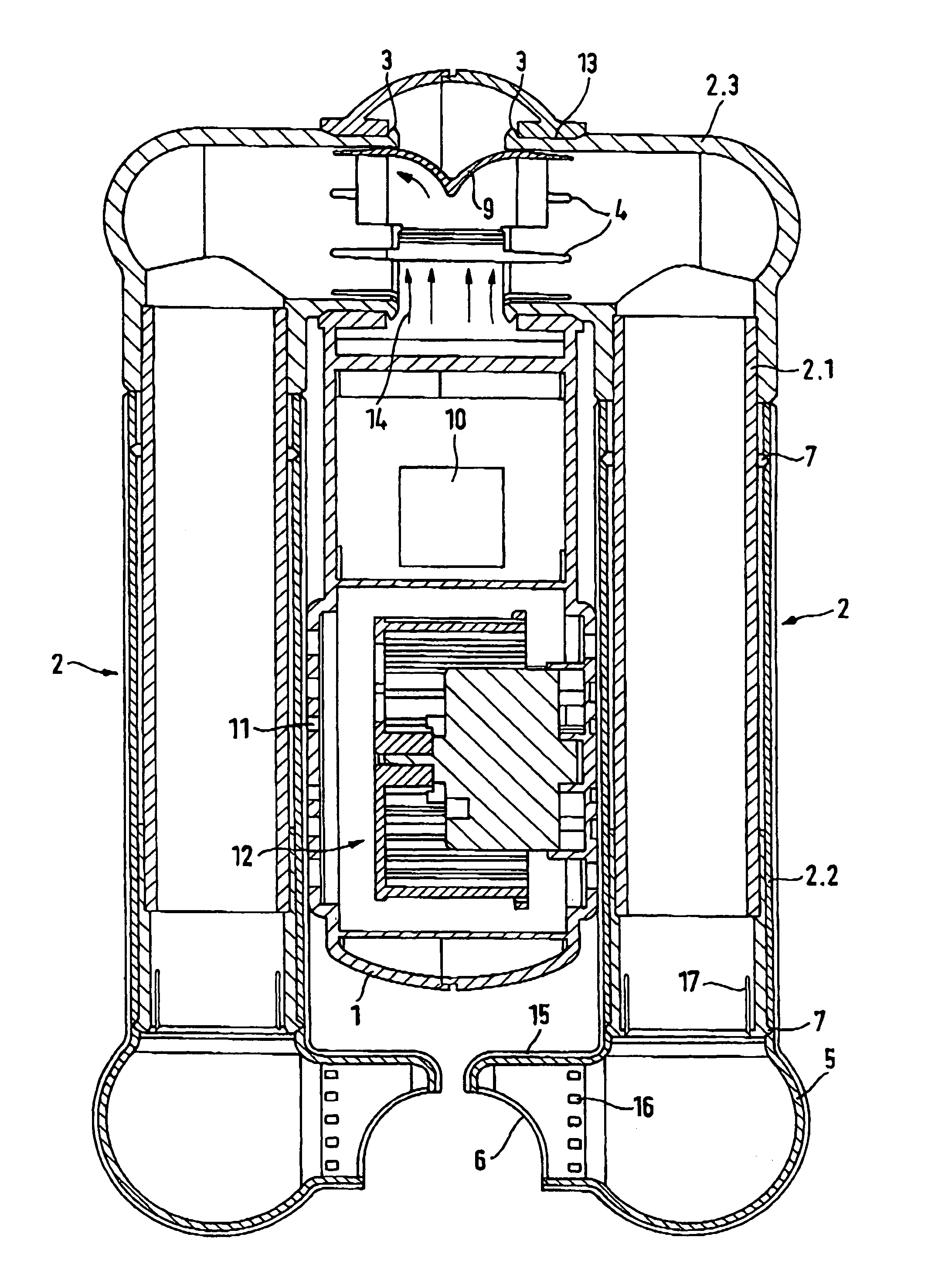
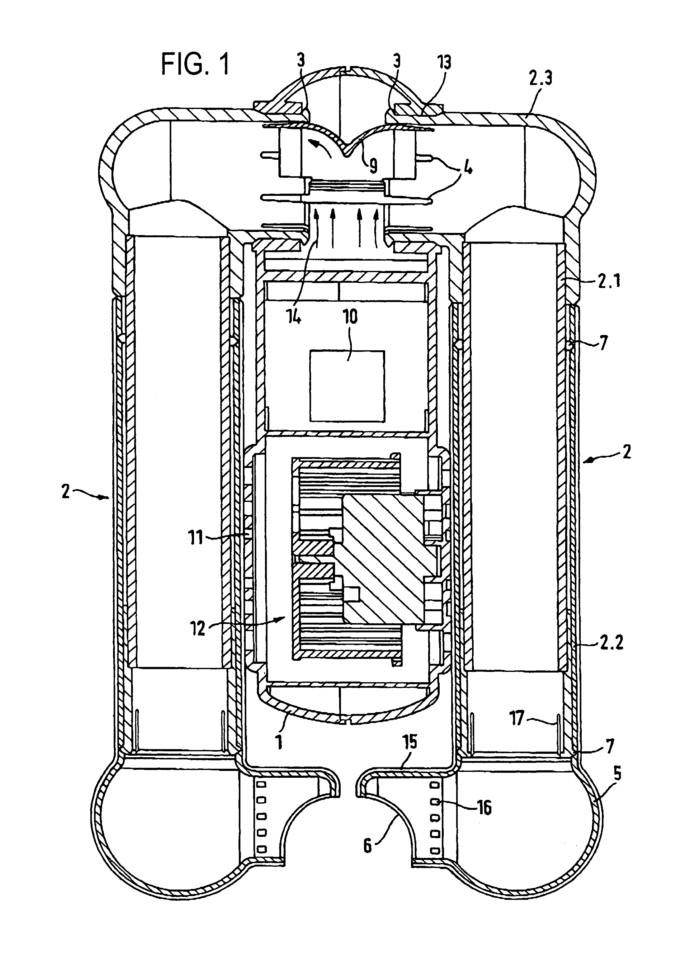
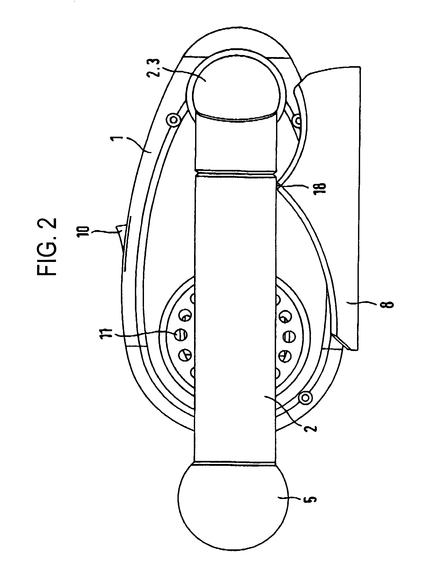
[0021]The apparatus shown in FIG. 1 and FIG. 2 for drying shoes, gloves or articles of clothing comprises a housing 1 and two pipes 2 which are attached to the housing and which are arranged directly adjacent to the housing 1 like arms. In the housing 1 are contained an electrically operated fan 12 as well as electrical components for driving the fan 12, wherein the electrical supply can be delivered via a cable, not shown, from mains and / or a battery and / or a chargeable accumulator. To switch the fan on and off, a switch 10 is embedded in a narrow side wall of the housing 1. In the region of the fan 12 the housing is provided with intake openings 11 through which air is drawn in from the outside by the fan. The fan 12 includes a fan housing which is adjoined by an air duct (not shown), wherein in the air duct is arranged a heating device, e.g. a radiator (not shown), which heats the air delivered by the fan 12.

[0022]In the upper region of the housing 1 (seen in the view as in FIG. ...


PUM


Abstract

The invention relates to a device for drying shoes, gloves or garments comprising a fan which produces an airflow and which is accommodated in a housing. The housing comprises two openings that are connected to two tube sockets which are arranged opposite one another and which are fastened to said housing. The tube sockets are connected to tubes for guiding the airflow. To this end, the tube sockets are angular and one end of each tube socket is rotatably connected to the housing while forming a swivel joint.

Description

CROSS REFERENCE TO RELATED APPLICATIONS[0001]This application is the U.S. National Phase of international patent application PCT / EP01 / 00946, filed on Jan. 30, 2001, and claiming priority to German utility model application number 200 01 932.5, filed Jan. 31, 2000, hereby incorporated by reference.FIELD OF THE INVENTION[0002]The invention concerns an apparatus for drying shoes, gloves or articles of clothing according to the introductory part of the main claim.BACKGROUND OF THE THE INVENTION[0003]Thus, in U.S. Pat. No. 5,720,108 is described a transportable drier for shoes and gloves. This drier consists of several component parts which can be connected to each other for use and housed separately during transport. With this drier, two flexible pipes or hoses can be connected to a housing in which is also contained a fan. In turn, air outlet nozzles can be attached to these flexible pipes or hoses. For adaptation to different required lengths, such as is the case for example for the d...

Claims


Application Information

Patent Timeline
Patent Type & Authority Patents(United States)
IPC IPC(8): F26B25/00A47L23/20D06F59/04F26B9/00F26B21/00
CPCA47L23/205D06F59/04F26B9/003F26B21/006
Inventor MACHER, DAVIDZORN, HEINZSCHREINER, GERHARD
Owner SIDAS CENT
Why Eureka
Try Eureka