Pet enclosure with dual axes swivel connector

a technology of swivel connectors and enclosures, applied in the field of collapsible enclosures, to achieve the effect of reducing noise, facilitating offsetting of panels, and reducing overall nois

Inactive Publication Date: 2012-11-01
DOSKOCIL MFG
View PDF15 Cites 8 Cited by
  • Summary
  • Abstract
  • Description
  • Claims
  • Application Information

AI Technical Summary

Benefits of technology

[0009]These dual axes swivel connectors may reduce noise as the pet enclosure is being transported in a car over a road. In particular, the panels may be fabricated from a metallic material whereas the swivel connectors may be fabricated from a plastic material. When the enclosure is traversed to the erected position, the various panels are generally supported between each other by the swivel connectors. The swivel connectors which may be fabricated from a plastic material behave as shock absorbers or vibration dampeners to reduce the overall noise caused by the rattling of the erected pet enclosure.
[0010]Additionally, when traversing the pet enclosure to the collapsed position, the panels which are typically fabricated from a metallic material generally do not bend. As such, the various panels must be offset at different height elevations as measured from the bottom panel when being stacked upon each other and on top of the bottom panel. If the adjacent panels are connected to each other through prior art Hartco clips, adjacent wires of the adjacent panels are looped together as discussed in the background section above. Unfortunately, the adjacent wires and the prior art Hartco clips may bind against each other preventing rotation of the adjacent panels and preventing the adjacent panels from being stacked upon each other at different heights. To this end, the dual axes swivel connector facilitates offsetting of the panels so that they may be stacked upon each other since the adjacent wires of adjacent panels do not bind within the dual axes swivel connector.
[0011]Moreover, the dual axes swivel connectors may be unidirectional. In particular, the dual axes swivel connector is mounted to edge rods of adjacent panels. Once the swivel connector is attached to adjacent edge rods of adjacent panels, it is not intended for the swivel connectors to be removed. To this end, the swivel connectors may have a tapered median that separates the adjacent edge rods from each other and pushes the respective edge rods deeper into grooves of the swivel connector to mitigate withdrawal of the edge rods out of the connectors once the edge rods are disposed in the grooves of the swivel connector. Moreover, retaining walls of the swivel connector may be sufficiently wrapped around the edge rods to mitigate pull out of the edge rods from the swivel connectors. Additionally, the tapered median prevents contact between adjacent edge rods of adjacent panels so that the edge rods do not bind or get stuck during pivoting of adjacent panels.
[0019]The first and second side panels and the top and bottom panels may be fabricated from a metallic material and the dual axes swivel connectors may be fabricated from a plastic material for mitigating noise.
[0022]The retaining walls may be connected to opposed distal end portions of the back wall. The retaining walls may be resilient so as to flex outward upon inserting the edge rods between distal end portions of the retaining walls and the proximal end portion of the tapered median to permit traversal of the edge rods into the two grooves and to flex inward around the edge rods thereafter. The resilient retaining walls may extend about 180 degrees from the opposed distal end portions of the back wall to mitigate removal of the edge rods from the two grooves after insertion. The distal end portions of the retaining walls and the distal end portion of the tapered median defines entrance gaps of the two grooves.
[0024]The second end portion may comprise a tapered median, a back wall and retaining walls. The tapered median may urge the edge rods into the two grooves. The tapered median may define a proximal end portion and a distal end portion. The back wall may be connected to the distal end portion of the tapered median. The back wall may extend laterally outward from the distal end portion of the tapered median to limit insertion of the edge rods into the two grooves. The retaining walls may be connected to opposed distal end portions of the back wall. The retaining walls may be resilient to flex outward upon inserting the edge rods between distal end portions of the resilient retaining walls and the distal end portion of the tapered median to permit traversal of the edge rods into the two grooves and to flex inward around the edge rods thereafter. The resilient retaining walls may extend about 180 degrees from the opposed distal end portions of the back wall to mitigate removal of the edge rods from the two grooves after insertion. The distal end portions of the retaining walls and the distal end portion of the tapered median may define entrance openings of the two grooves.

Problems solved by technology

Unfortunately, the adjacent wires and the prior art Hartco clips may bind against each other preventing rotation of the adjacent panels and preventing the adjacent panels from being stacked upon each other at different heights.

Method used


Image

  • Pet enclosure with dual axes swivel connector
  • Pet enclosure with dual axes swivel connector
  • Pet enclosure with dual axes swivel connector

Examples


Embodiment Construction

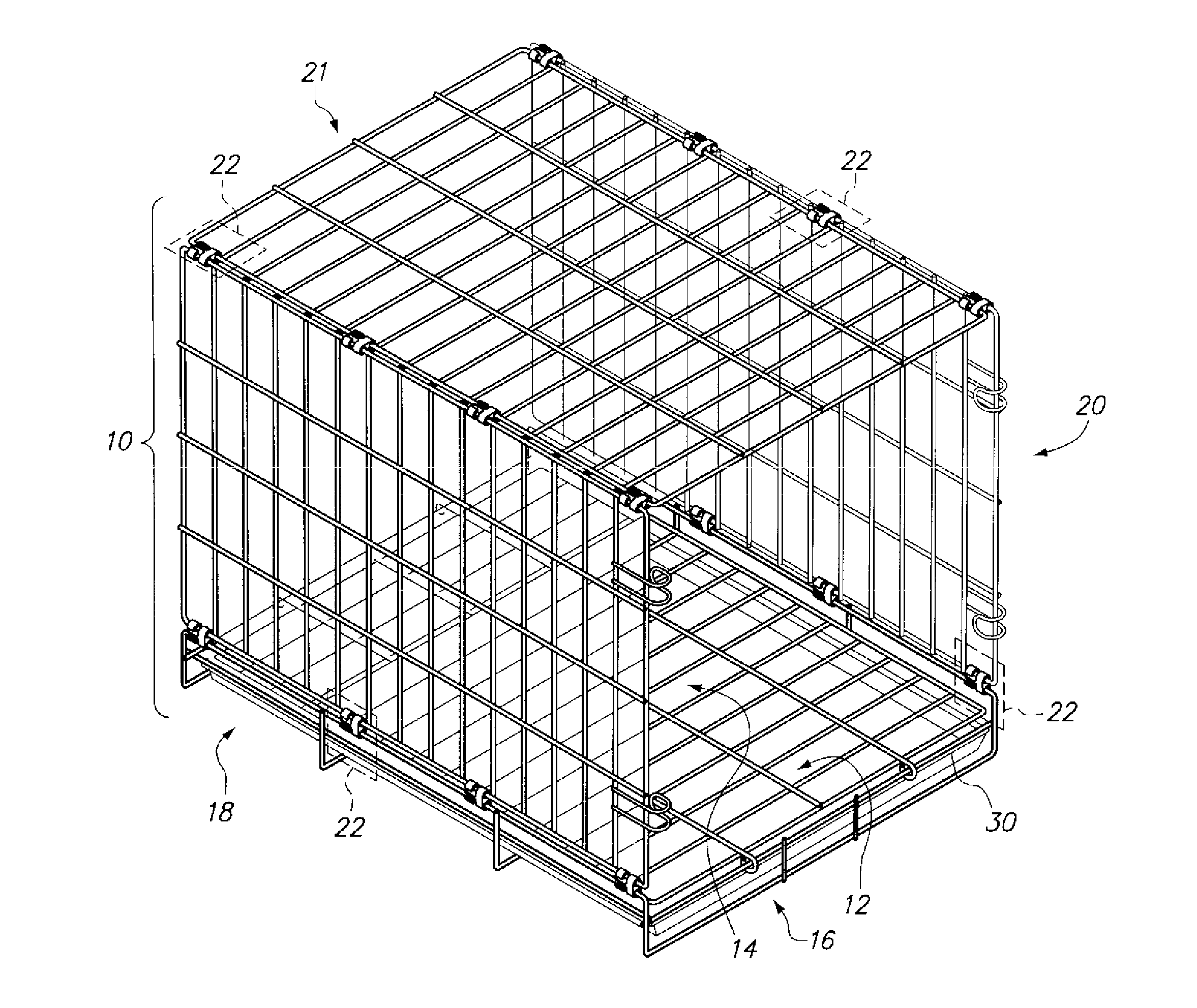
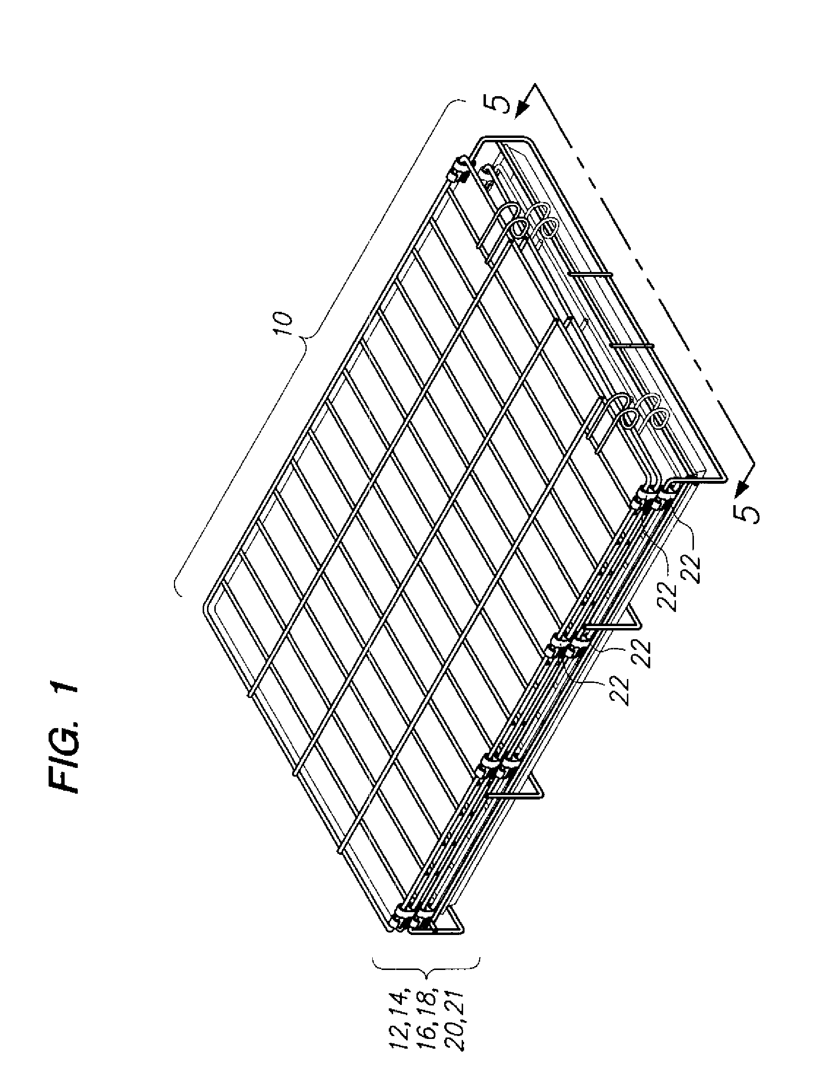
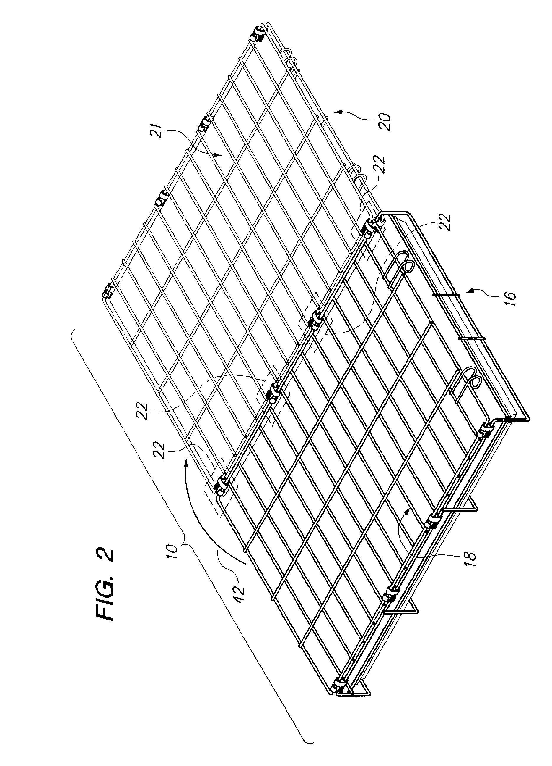
[0069]Referring now to the drawings, a collapsible enclosure 10 is shown. When the enclosure 10 is in storage or being transported, the enclosure 10 may be traversed to the collapsed position shown in FIG. 1. During use, the enclosure 10 may be traversed to the erected position shown in FIG. 3. FIG. 3 illustrates the erected position of the enclosure 10 with front and back panels 12, 14 still in the folded configuration. The various panels, namely, a bottom panel 16, left and right side panels 18, 20 and top panel 21 may be rotatably connected to each other by way of a dual axes swivel connector 22, 100. A first embodiment of the dual axes swivel connector 22 is shown and described in relation to FIGS. 1-12. A second embodiment of the dual axes swivel connector 100 is shown and described in relation to FIGS. 13-17. It is also contemplated that the front and back panels 12, 14 may be rotatably connected to the bottom panel 16 by way of the dual axes swivel connector 22, 100.

[0070]Ref...


PUM

PropertyMeasurementUnit
elevationsaaaaaaaaaa
elevationaaaaaaaaaa
areaaaaaaaaaaa

Abstract

A dual axes swivel connector for connecting various panels to assemble a pet enclosure is disclosed. The dual axes swivel connector allows panels of the enclosure to be reliably pivoted with respect to each other. The dual axes swivel connector may comprise first and second parts. The first part may be fabricated from a flexible material compared to the second part, whereas the second part may be fabricated from a more rigid material compared to the first part. The flexibility of the first part allows the first part to have a tighter fit with the wire rods. The second part has a looser fit with the wire rods but the rigidity of the second part compensates for the looser fit. When the first and second parts are interlocked, they create a tight fit which can reliably provide a hinge between the panels.

Description

CROSS-REFERENCE TO RELATED APPLICATIONS[0001]This is a continuation in part application of U.S. patent application Ser. No. 13 / 045,411, filed on Mar. 10, 2011, the entire contents of which are incorporated herein by reference.STATEMENT RE: FEDERALLY SPONSORED RESEARCH / DEVELOPMENT[0002]Not ApplicableBACKGROUND[0003]The present invention relates to a collapsible enclosure (e.g., pet enclosure).[0004]Pet or animal enclosures are commonly used to accommodate, confine or transport pets or animals. Currently, prior art pet enclosures are fabricated from a wire frame wherein the various panels are hinged to each other by way of Hartco clips. Hartco clips are wrapped around adjacent wires of adjacent panels so as to form a loop around the adjacent wires. The adjacent panels can pivot or rotate with respect to each other due to the space provided in the enclosed loop. Unfortunately, the wires of the adjacent panels may bind within the loop (i.e., Hartco clip) when being rotated with respect ...

Claims


Application Information

Patent Timeline
Patent Type & Authority Applications(United States)
IPC IPC(8): A01K1/03F16C11/04B23P17/00A01K1/00
CPCA01K3/00E05D3/12Y10T24/344Y10T29/49716E05Y2900/40A01K1/034A01K1/0017Y10T24/3444Y10T403/32606Y10T403/32008E05D5/127A01K1/0005F16C11/04
Inventor LINK, DAVIDLIANG, HONGKUN
Owner DOSKOCIL MFG
Why Eureka
Try Eureka