Touch panel

a technology of touch panel and touch screen, applied in the field of touch panel, can solve the problems of inability to easily obtain, restrict the origin of the indium, and the price of the indium is relatively high, and achieve the effect of favorable visual

Inactive Publication Date: 2015-04-23
WINTEK CORP
View PDF1 Cites 33 Cited by
  • Summary
  • Abstract
  • Description
  • Claims
  • Application Information

AI Technical Summary

Benefits of technology

[0008]The present invention is directed to a touch panel capable of providing a favorable visual effect.
[0011]Based on the above, the touch panel of the invention composes the first and the second electrodes by using the mesh patterns of the metal material. Accordingly, in comparison with the touch panel using indium tin oxide containing rare earth element indium as the material of the electrode pads, the material used in the invention may be easily obtained, and a price of the material is also inexpensive. Moreover, the intersections of the first and the second electrodes are formed by the mesh patterns being overlapped, and the outer contours of the first electrode pads and the second electrode pads are defined by the zigzag lines. Therefore, the touch panel of the invention may facilitate in lowering a probability of the outer contours of the first and the second electrodes and the intersections being noticed by the user, so that the touch panel may provide a favorable visual effect.

Problems solved by technology

However, indium is a rare metal and cannot be easily obtained for such material is prone to restriction of its place of origin.
Moreover, since a price of indium is relatively expensive, manufacturing costs for the touch panel cannot be reduced, thus it is disadvantageous in commercial competitiveness.
However, a difference between a reflective index of the metal bridge and a reflective index of the electrode pad is overly huge.

Method used


Image

  • Touch panel
  • Touch panel
  • Touch panel

Examples


first embodiment

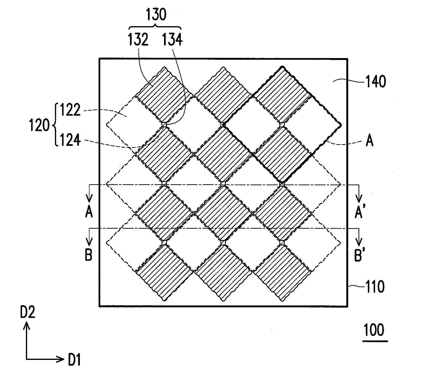
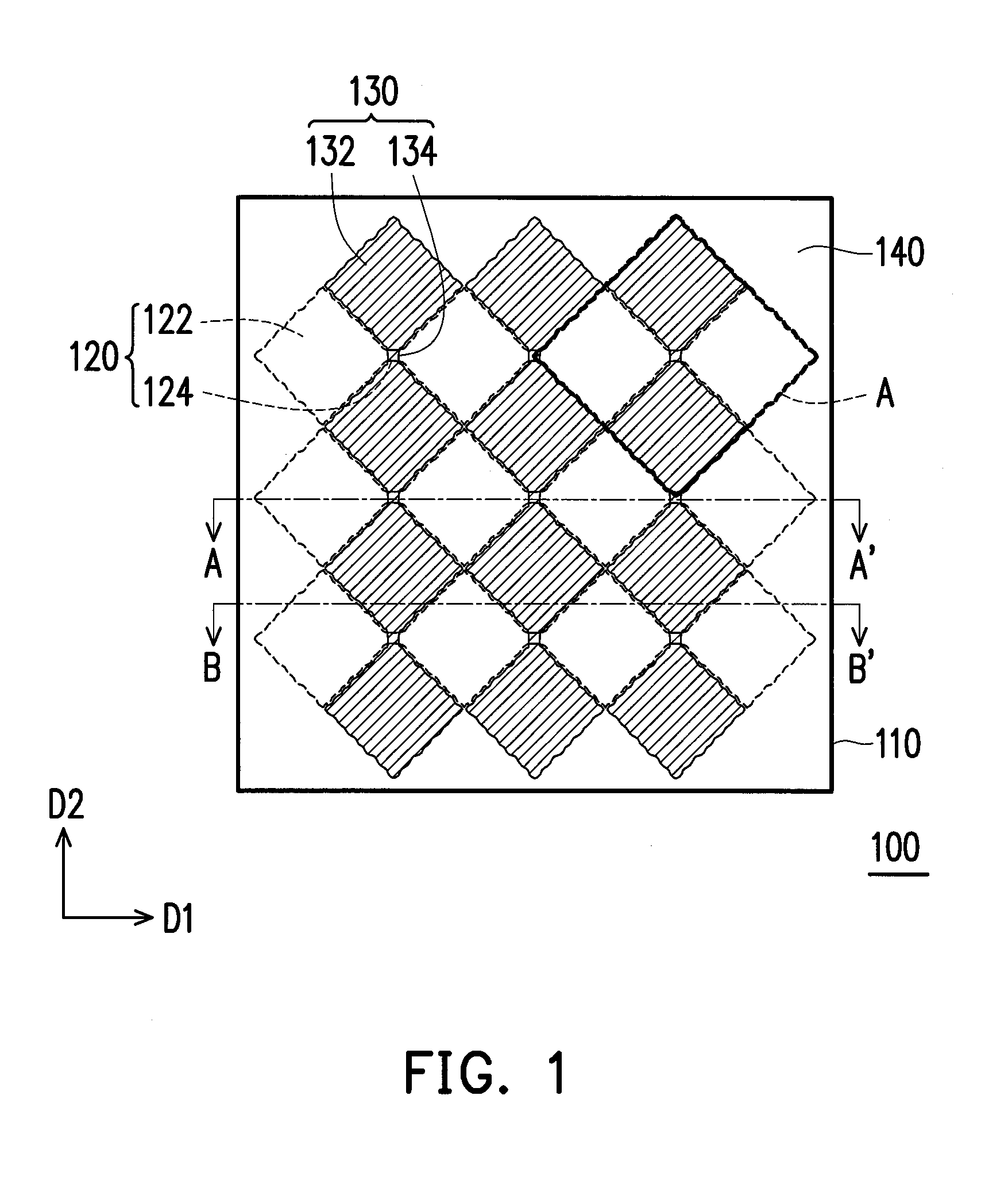
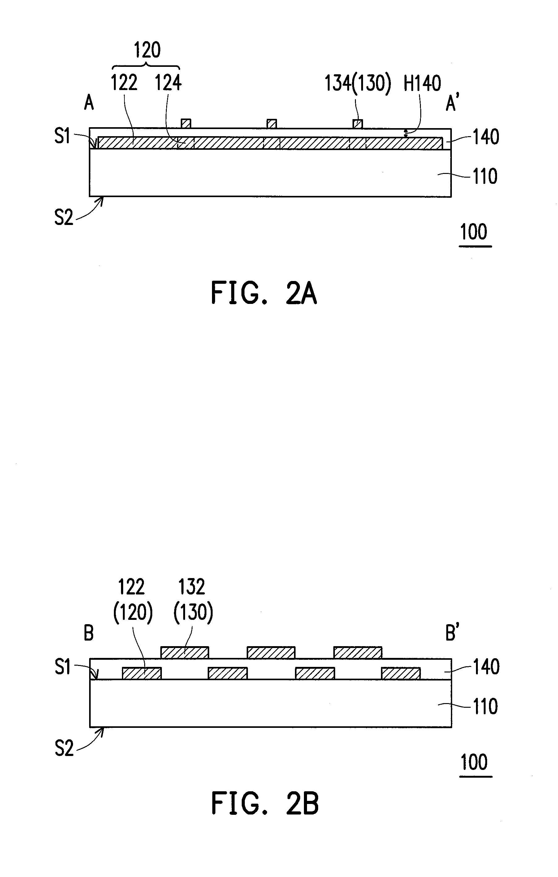
[0024]FIG. 1 is a schematic top view of a touch panel of the invention. FIGS. 2A and 2B are schematically sectional views along section lines A-A′ and B-B′ depicted in FIG. 1, respectively. FIG. 3A is an explosion diagram of the first electrode and the second electrode in a region A depicted in FIGS. 1, and 3B is an enlarged view of the region A depicted in FIG. 1. Referring to FIGS. 1, 2A and 2B, a touch panel 100 of the present embodiment includes a substrate 110, a plurality of first electrodes 120 and a plurality of second electrodes 130.

[0025]The first electrodes 120 are disposed on the substrate 110. Each of the first electrodes 120 includes a plurality of first electrode pads 122 and a plurality of first connecting lines 124, and each of the first connecting lines 124 connects adjacent two of the first electrode pads 122 in series. The second electrodes 130 are electrically insulated from the first electrodes 120 and disposed on the substrate 110, and each of the second elec...

second embodiment

[0055]FIG. 5 is a schematically sectional view of a touch panel of the invention. Referring to FIG. 5, a touch panel 200 of the present embodiment includes a structure similar to that of the touch panel 100 of FIG. 2B, and the first electrode 120 and the second electrode 130 of the touch panel 200 may be stacked by adopting the methods depicted in FIGS. 3B-4G. Therein, the same layers are indicated by the same reference numbers, thus materials, disposition and effects of the layers are omitted hereinafter. Unlike the touch panel 100, the touch panel 200 of the present embodiment further includes optical absorption layers 150 and 160 located on a surface of the first electrode 120 and the second electrode 130 facing a user, so as to further improve a visual effect of the touch panel 200. In the present embodiment, the substrate 110 is, for example, a cover plate; a surface S1 is, for example, a surface for disposing elements; and a surface S2 opposite to the surface S1 is, for examp...

third embodiment

[0058]FIG. 6 is a schematically sectional view of a touch panel of the invention. Referring to FIG. 6, a touch panel 300 of the present embodiment includes a structure similar to that of the touch panel 200 of FIG. 5, and the first electrode 120 and the second electrode 130 of the touch panel 300 may be stacked by adopting the methods depicted in FIGS. 3B-4G. Therein, the same layers are indicated by the same reference numbers, thus materials, disposition and effects of the layers are omitted hereinafter. Unlike the touch panel 200, the substrate 110 of the touch panel 300 of the present embodiment is merely used to bear above-said layers, and the touch panel 300 may further include a cover plate CG and an adhesion layer AD. Therein, the first electrodes 120 and the second electrodes 130 are located between the substrate 110 and the cover plate CG, and the cover plate CG is bonded to the substrate 110 and the layers thereon through the adhesion layer AD, such that the adhesion laye...


PUM


Abstract

A touch panel including a substrate, first electrodes and second electrodes is provided. The first electrodes and the second electrodes are electrically insulated from each other and are disposed on the substrate. Each first electrode includes first electrode pads and first connecting lines, and the first connecting lines connect adjacent two of the first electrode pads in series. Each second electrode includes second electrode pads and second connecting lines, and the second connecting lines connect adjacent two of the second electrode pads in series. An outer contour of each first electrode pad is defined by a first zigzag line, an outer contour of each second electrode pad is defined by a second zigzag line, and the first zigzag line and the second zigzag line located at a boundary between the first electrode and the second electrode are parallel or partially parallel to each other.

Description

CROSS-REFERENCE TO RELATED APPLICATION[0001]This application claims the priority benefit of Taiwan application serial no. 102137878, filed on Oct. 18, 2013, and Taiwan application serial no. 103129877, filed on Aug. 29, 2014. The entirety of each of the above-mentioned patent applications is hereby incorporated by reference herein and made a part of this specification.BACKGROUND OF THE INVENTION[0002]1. Field of the Invention[0003]The invention relates to a panel, and more particularly, to a touch panel.[0004]2. Description of Related Art[0005]With rapid developments and applications of the information technology, wireless mobile telecommunication, and information appliances, the input devices of many information products are changed from traditional input device such as a traditional keyboard, a mouse to a touch panel, so as to satisfy the requirements of convenience in carrying, light weight, and user-friendly operations.[0006]The touch panel is generally categorized into a resist...

Claims


Application Information

Patent Timeline
Patent Type & Authority Applications(United States)
IPC IPC(8): G06F3/044
CPCG06F3/044G06F2203/04103G06F2203/04112G06F3/0445G06F3/0446
Inventor CHOU, RONE-HWAFANG, CHONG-YANGHSU, CHING-FUTSENG, YING-CHINGKANG, HEN-TAWU, FA-CHENWANG, WEN-CHUN
Owner WINTEK CORP
Why Eureka
Try Eureka