Wiper arm and vehicle wiper apparatus equipped therewith

a technology of wipers and hoses, which is applied in the direction of vehicle maintenance, vehicle cleaning, domestic applications, etc., can solve the problems of increasing the number of components, affecting so as to improve ensure the stability of the hoses. , the effect of reducing the number of components and excellent wiping performan

Active Publication Date: 2015-04-30
DENSO CORP
View PDF10 Cites 23 Cited by
  • Summary
  • Abstract
  • Description
  • Claims
  • Application Information

AI Technical Summary

Benefits of technology

[0012]According to the wiper arm with the structure described above, the arm main body of the wiper arm has a cross-sectional shape in the direction orthogonal to the arm length direction in a substantial letter-U shape. The two-line hose, the first line hose connected to the first nozzle portion and the second line hose connected to the second nozzle portion, are accommodated side-by-side in the arm main body. When the washing fluid is supplied to the first line hose, the washing fluid is jetted from the jetting hole of the first nozzle portion. When the washing fluid is supplied to the second line hose, the washing fluid is jetted from the jetting hole of the second nozzle portion toward a position different from an impact position of the washing fluid jetted from the jetting hole of the first nozzle portion. Thus, with the wiper arm according to the present invention, a two-line hose may be used to form the washing fluid from the nozzle portions provided at two locations into distinctively different jets. Thus, compared to a case of jetting washing fluid from nozzle portions provided at two locations of a single-line hose (for example, the related art recited in Japanese Patent Application National Publication No. 2002-536244), excellent wiping performance can be obtained.
[0013]In the present invention, the hose retention unit is attached to the arm main body. The first line hose is retained by the first hose retention portion provided at the hose retention unit, and the second line hose is retained by the second hose retention portion provided at the hose retention unit. Thus, the hose retention portions are provided one for each hose. Therefore, the state of arrangement of the first line hose and the second line hose is not complicated by angular motions of the wiper arm, and a stable state of arrangement may be maintained. Moreover, because the second hose retention portion is provided integrally with the first hose retention portion, the number of components is reduced compared to a structure in which hose retention portions are provided separately for the respective hoses.

Problems solved by technology

Therefore, managing the hoses to keep them stable is difficult.
In particular, because the hoses are made of rubber, a hose subjected to an external force may lose its connection or be easily bent into a kink or the like, so appropriate jetting of the washing fluid may be impeded.
Moreover, because an increase in the number of components in association with an improvement would lead complicate assembly operations, it is desirable to greatly suppress any increase in the number of components.

Method used


Image

  • Wiper arm and vehicle wiper apparatus equipped therewith
  • Wiper arm and vehicle wiper apparatus equipped therewith
  • Wiper arm and vehicle wiper apparatus equipped therewith

Examples


Embodiment Construction

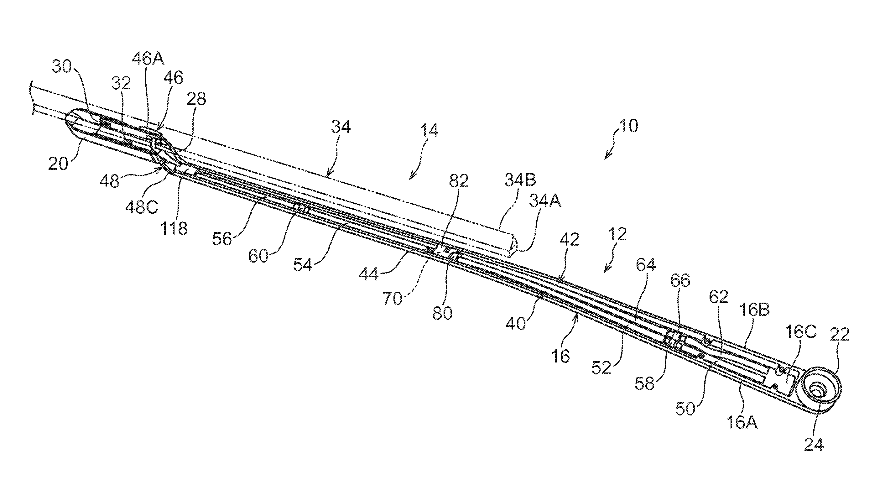
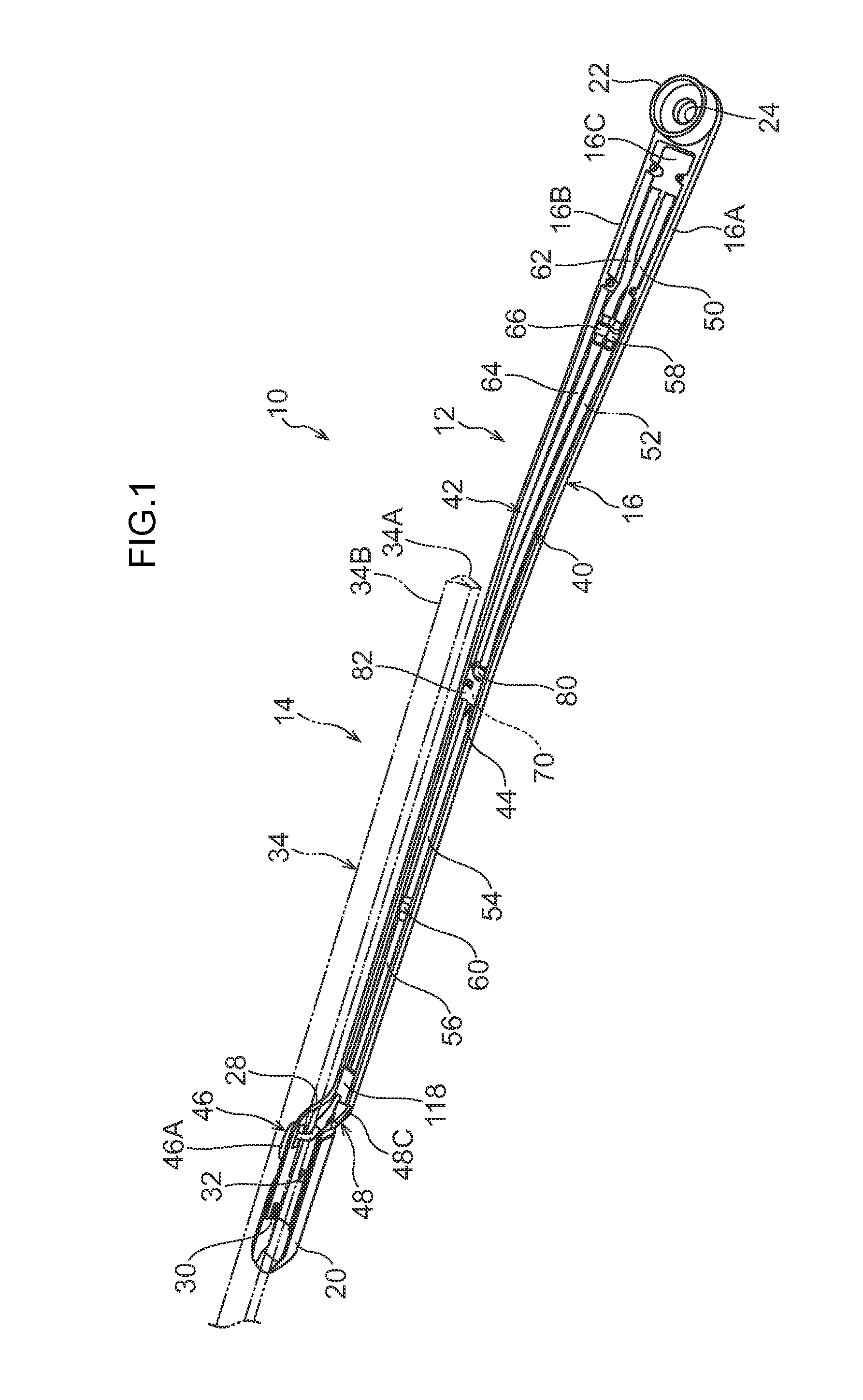
[0028]Herebelow, a vehicle wiper apparatus 10 in accordance with an exemplary embodiment of the present invention is described using FIG. 1 to FIG. 11B.

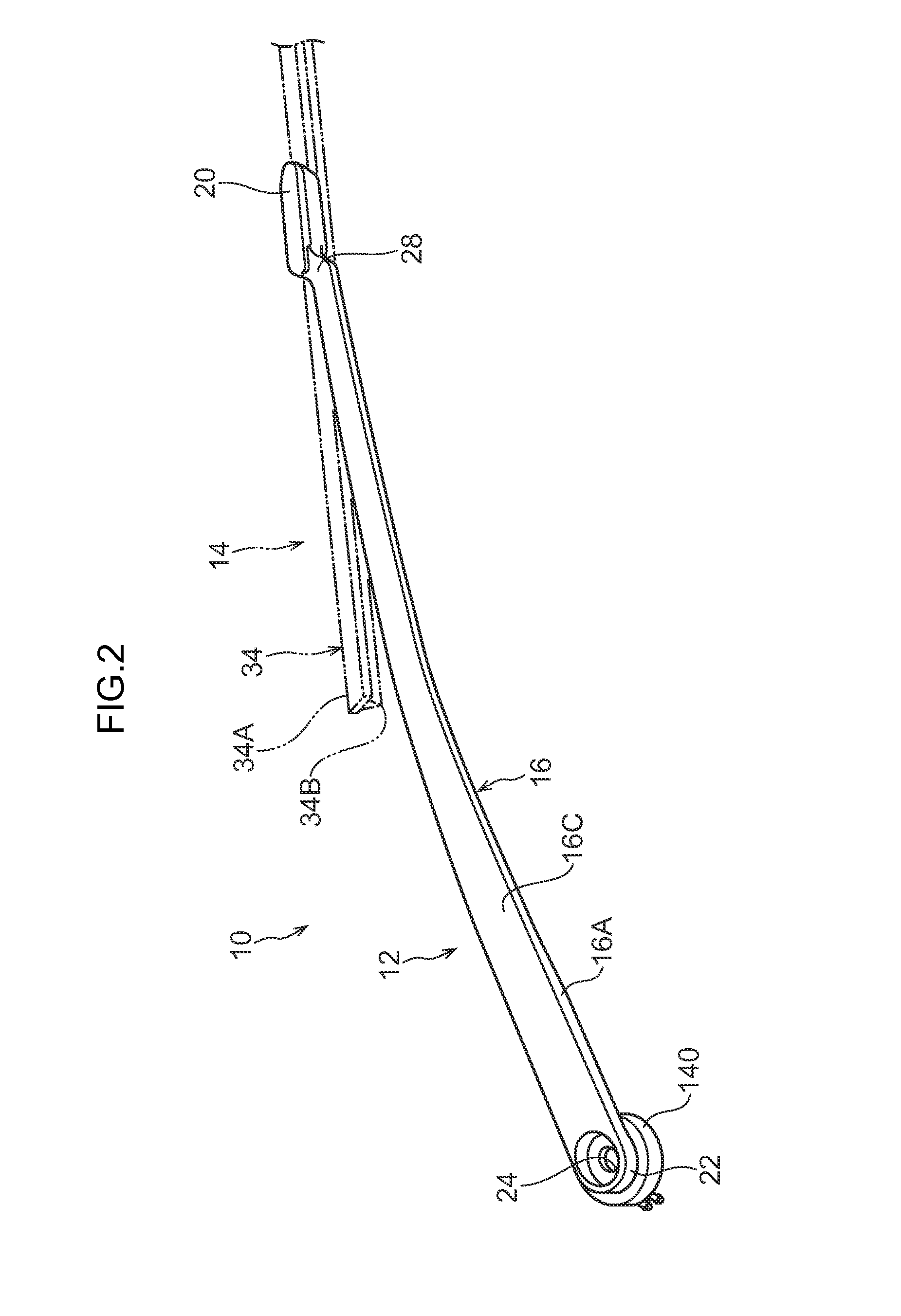
[0029]As shown in FIG. 3, the vehicle wiper apparatus 10 is structured with wiper arms 12 formed substantially in long, narrow shapes, and wiper blades 14 that wipe a wiped surface S of a windshield glass WG of the vehicle. First, the overall structure of the vehicle wiper apparatus 10 is outlined using FIG. 1 to FIG. 3.

[0030]—Overall Structure of the Wiper Arm 12—

[0031]As shown in FIG. 1 and FIG. 2, the exterior of each wiper arm 12 is structured by an arm main body 16, a rear face cover (not shown in the drawings) and a distal end cover 20. The arm main body 16 has an open cross-section structure, formed in a long, narrow shape. The rear face cover closes off a floor portion of the arm main body 16. The distal end cover 20 is attached to a distal end portion of the arm main body 16. Each of the arm main body 16, the rear face cover...


PUM


Abstract

A wiper arm comprising an arm main body; a first nozzle portion disposed at a first predetermined position in a length direction of the arm main body; a second nozzle portion disposed at a second predetermined position in the length direction of the arm main body, and jets washing fluid toward a position that is different from an impact point of the washing fluid jetted from the first nozzle portion; a first line hose accommodated in the arm main body and connected to the first nozzle portion; a second line hose accommodated in the arm main body side-by-side with the first line hose and connected to the second nozzle portion; and a hose retention unit attached to the arm main body and that comprises: a first hose retention portion retaining the first line hose; and a second hose retention portion provided integrally with the first hose retention portion and retaining the second line hose.

Description

CROSS-REFERENCE TO RELATED APPLICATION[0001]This application claims priorities under 35 USC 119 from Japanese Patent Applications No. 2013-223713 filed Oct. 28, 2013 and No. 2013-229648 filed Nov. 5, 2013, the disclosures of which are incorporated by reference herein.BACKGROUND OF THE INVENTION[0002]1. Technical Field[0003]The present invention relates to a wiper arm equipped with a nozzle that jets a washing fluid and to a wiper apparatus for a vehicle that is equipped with the wiper arm.[0004]2. Related Art[0005]Vehicle wiper apparatuses include an apparatus in which a washing fluid is jetted (supplied) from a washer nozzle mounted at a wiper arm to a wiping direction forward side of a wiper blade. For example, in (a wiper arm of) a vehicle wiper apparatus disclosed in Japanese Patent Application National Publication No. 2002-536244, a structure is employed in which respective washer nozzles are disposed at a length direction intermediate portion and distal end portion of the wipe...

Claims


Application Information

Patent Timeline
Patent Type & Authority Applications(United States)
IPC IPC(8): B60S1/52
CPCB60S1/522B60S1/482
Inventor UMENO, TAKASHI
Owner DENSO CORP
Why Eureka
Try Eureka