Signal Transmission Reducing Coupling Caused Delay Variation

a signal transmission and delay variation technology, applied in the field of electric signaling, can solve problems such as difficulties in achieving “late mode” timing and difficulties in achieving “early mode”

Inactive Publication Date: 2015-05-07
IBM CORP
View PDF5 Cites 0 Cited by
  • Summary
  • Abstract
  • Description
  • Claims
  • Application Information

AI Technical Summary

Benefits of technology

[0016]In an embodiment of the invention, one or more repowering blocks are placed along both the even signal path and the odd signal path. Eac

Problems solved by technology

The timing uncertainties described briefly above may cause significant increases in signal propagation times resulting in difficulties in achieving “late mode” timing as the signals may arrive too late and not be rel

Method used


Image

  • Signal Transmission Reducing Coupling Caused Delay Variation
  • Signal Transmission Reducing Coupling Caused Delay Variation
  • Signal Transmission Reducing Coupling Caused Delay Variation

Examples


Embodiment Construction

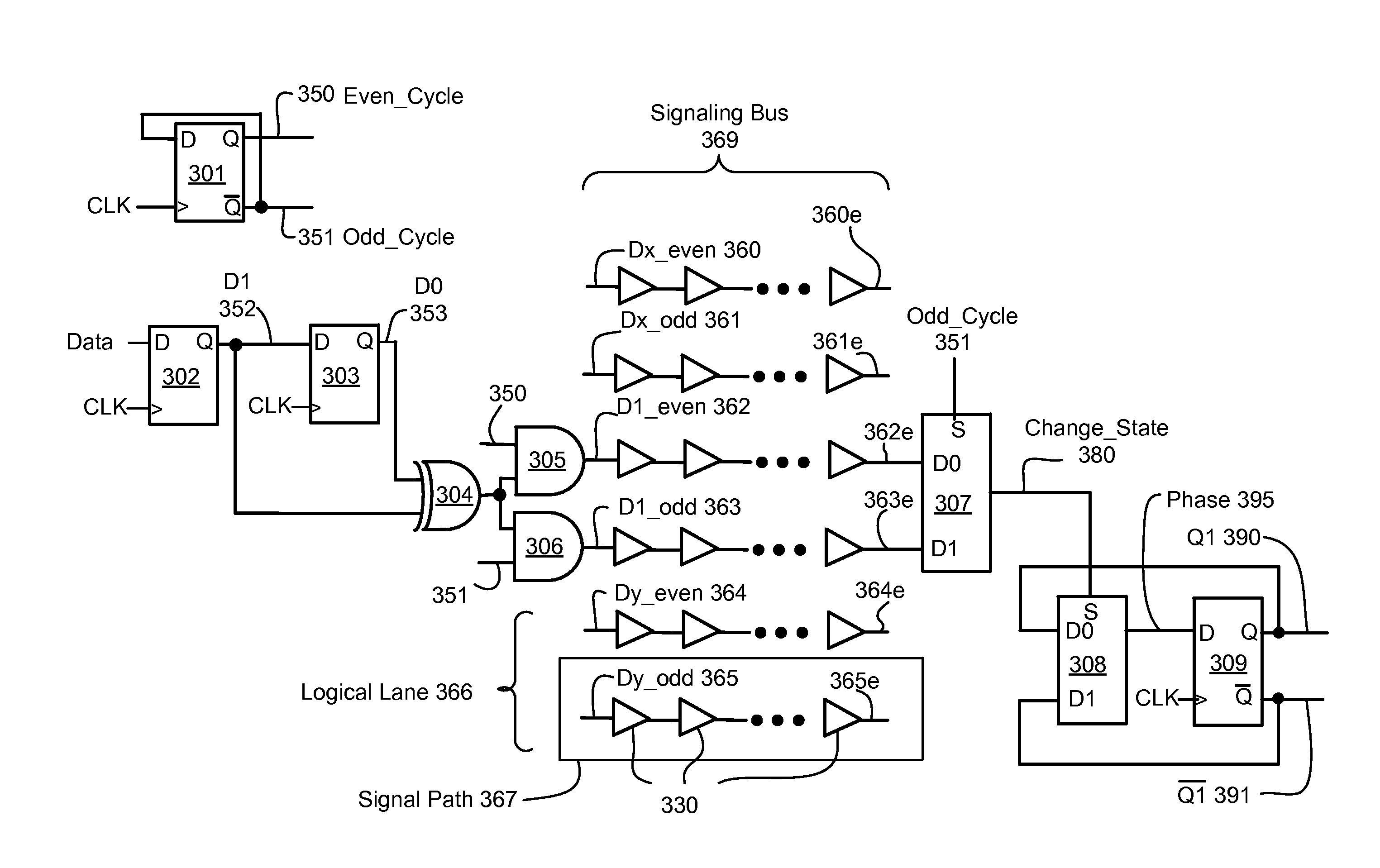
[0011]Embodiments of the invention provide reduction or elimination of coupling caused delay variations in a signaling bus. Embodiments of the invention provide for fast transition rates for signals of a first transition direction and slower (and / or delayed) transition rates for signals of a second direction, allowing repowering blocks to switch at a switching threshold that speeds signals of the first transition direction versus signals of the second direction.

[0012]In a method embodiment of the invention a signaling bus has a plurality of logical lanes, each logical lane being physically adjacent to at least one other logical lane. Each logical lane comprises an even signal path and an odd signal path. The method ensures that a one cycle path having a first transition direction transmitted on a first signal path in the signaling bus never encounters a one cycle signal having a second transition transmitted on an adjacent second signal path in the signaling bus.

[0013]In an apparatu...


PUM


Abstract

A signaling bus having a plurality of adjacent logical lanes, each logical lane having an odd signal path and an even signal path. Driving circuitry drives each logical lane by transmitting, if data has changed from an immediately preceding cycle, a one cycle signal having a first transition direction on the even signal path on even cycles and transmitting a one cycle signal having the first transition direction on odd cycles. If data has not changed, transmitting a two cycle signal having a second transition direction on the even signal path on even cycles and transmitting a two cycle signal on the odd path having the second transition direction on odd cycles. Receiver circuitry alternates selection of the even cycle path and the odd cycle path to determine if data has changed from the immediately preceding cycle.

Description

FIELD OF THE INVENTION[0001]This invention relates generally to electrical signaling. More specifically the invention relates to reducing transition time degradation and delay on a signal path caused by neighboring signal paths switching.BACKGROUND OF THE INVENTION[0002]Having reference now to prior art FIG. 1A, a conventional signaling arrangement 100 is shown, having a plurality of drivers in block 101, a plurality of receivers in block 150 to receive signals driven by the plurality of drivers in block 101, and a plurality of signal paths 120 (120A, 120B, 120C are referenced) to couple the plurality of drivers in block 101 to the plurality of receivers in block 150.[0003]In FIG. 1B, three signal paths 120 (120A, 120B, 120C) are depicted, with parasitic capacitors 130 (130AB, 130BC) coupling signal path 120B to adjacent neighbors 120A and 120C. It is well known thatI=C*dV / dt[0004]When signal paths 120A and 120C are not switching, transition rate d(V−Gnd) / dt, on signal path 120B wil...

Claims


Application Information

Patent Timeline
IPC IPC(8): G06F13/40G06F1/08
CPCG06F1/08G06F13/4022H04L25/00G06F13/4077
Inventor ALLEN, DAVID H.DEWANZ, DOUGLAS M.PAULSEN, DAVID P.SHEETS, II, JOHN E.
Owner IBM CORP
Why Eureka
Try Eureka