Magnetorheological fluid damper

Active Publication Date: 2015-05-14
KYB CORP
View PDF10 Cites 5 Cited by
  • Summary
  • Abstract
  • Description
  • Claims
  • Application Information

AI Technical Summary

Benefits of technology

[0009]The present invention was developed in view of the above problems and aims to provide a

Problems solved by technology

However, since the bypass flow passage is configured to penetrate through the piston and be open on the both ends of the piston in such a magnetorheological fluid damper, holes defining the bypass flow passage need to be formed in a plurality of members constituting the pisto

Method used


Image

  • Magnetorheological fluid damper
  • Magnetorheological fluid damper
  • Magnetorheological fluid damper

Examples


Example

First Embodiment

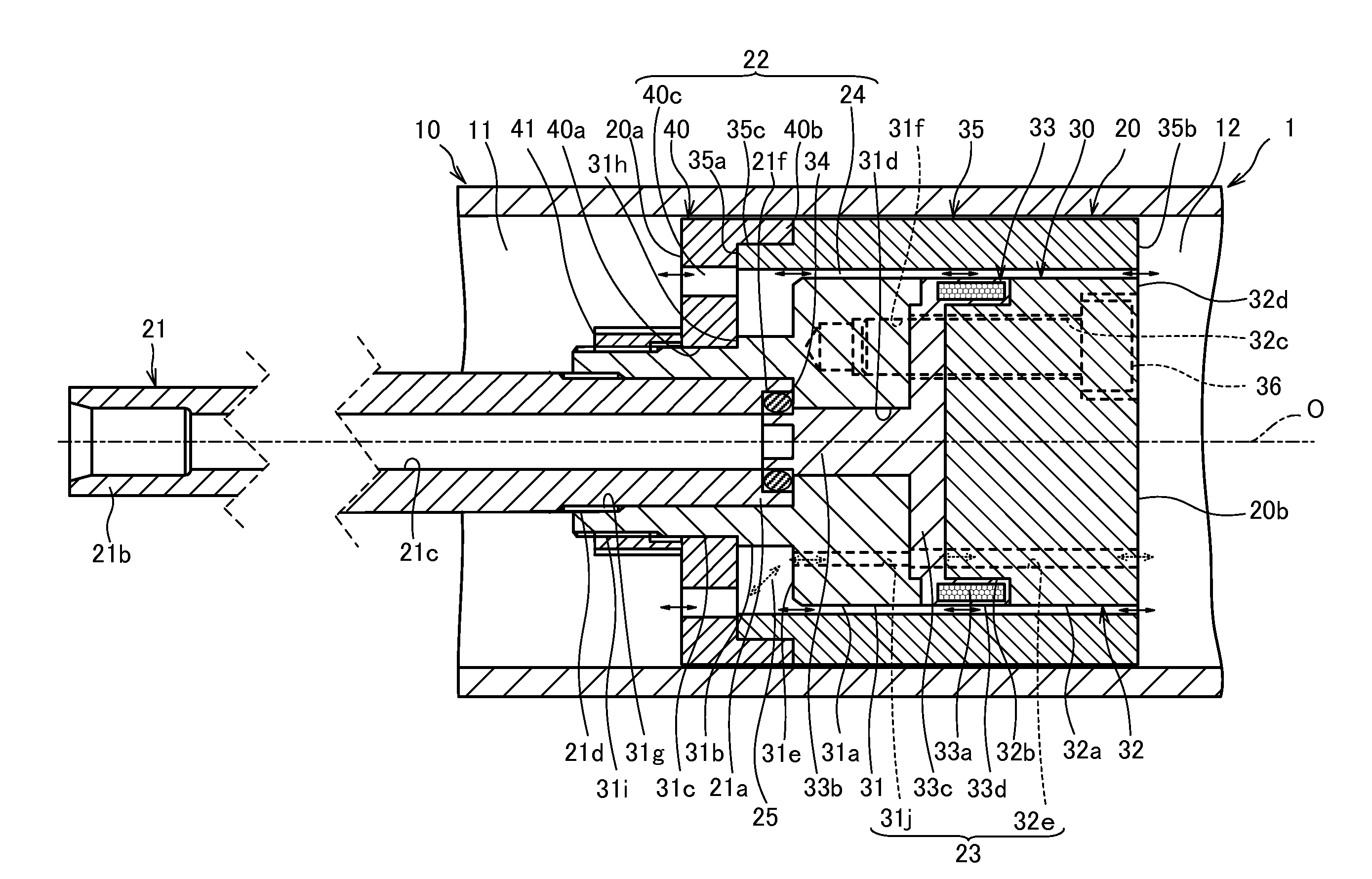
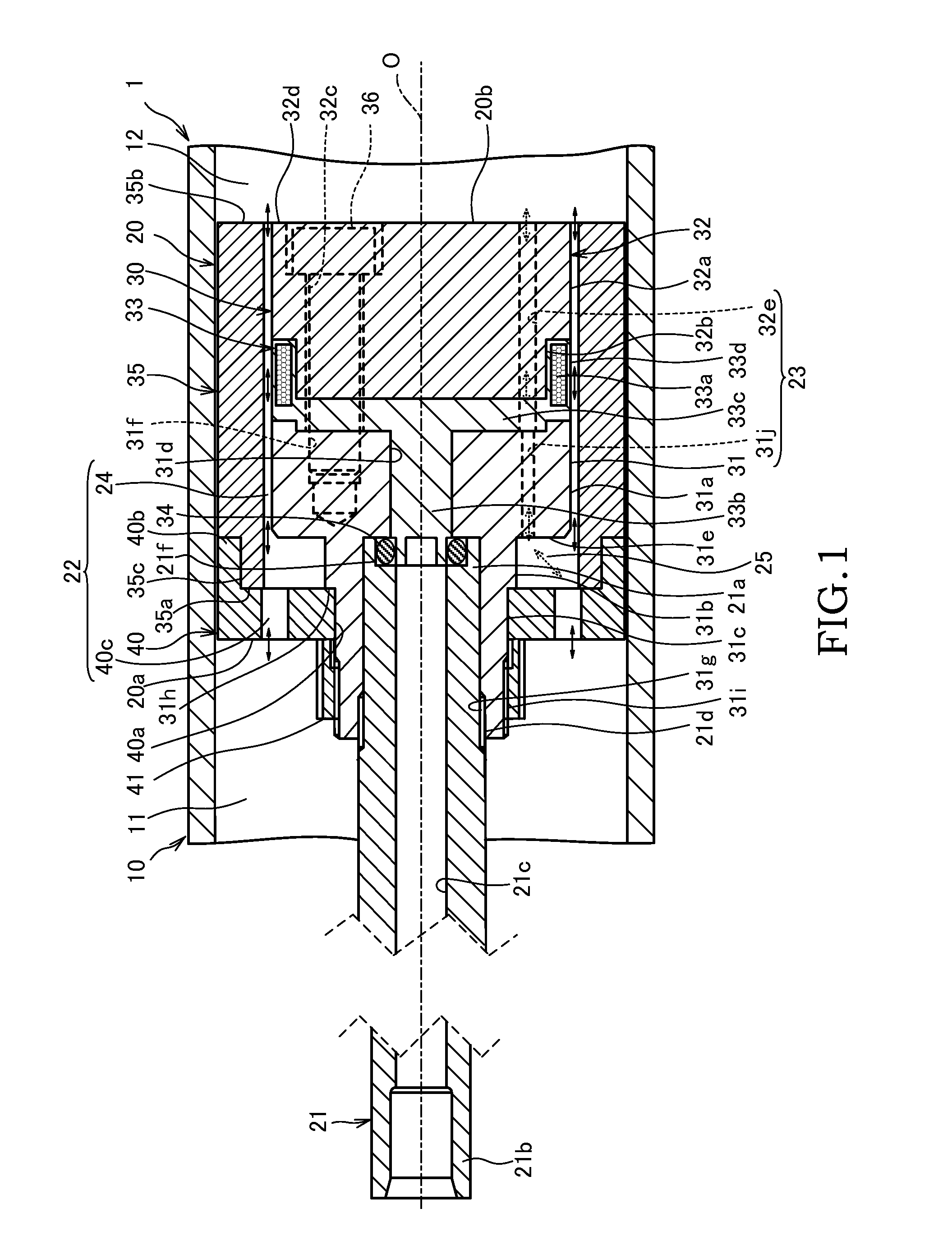
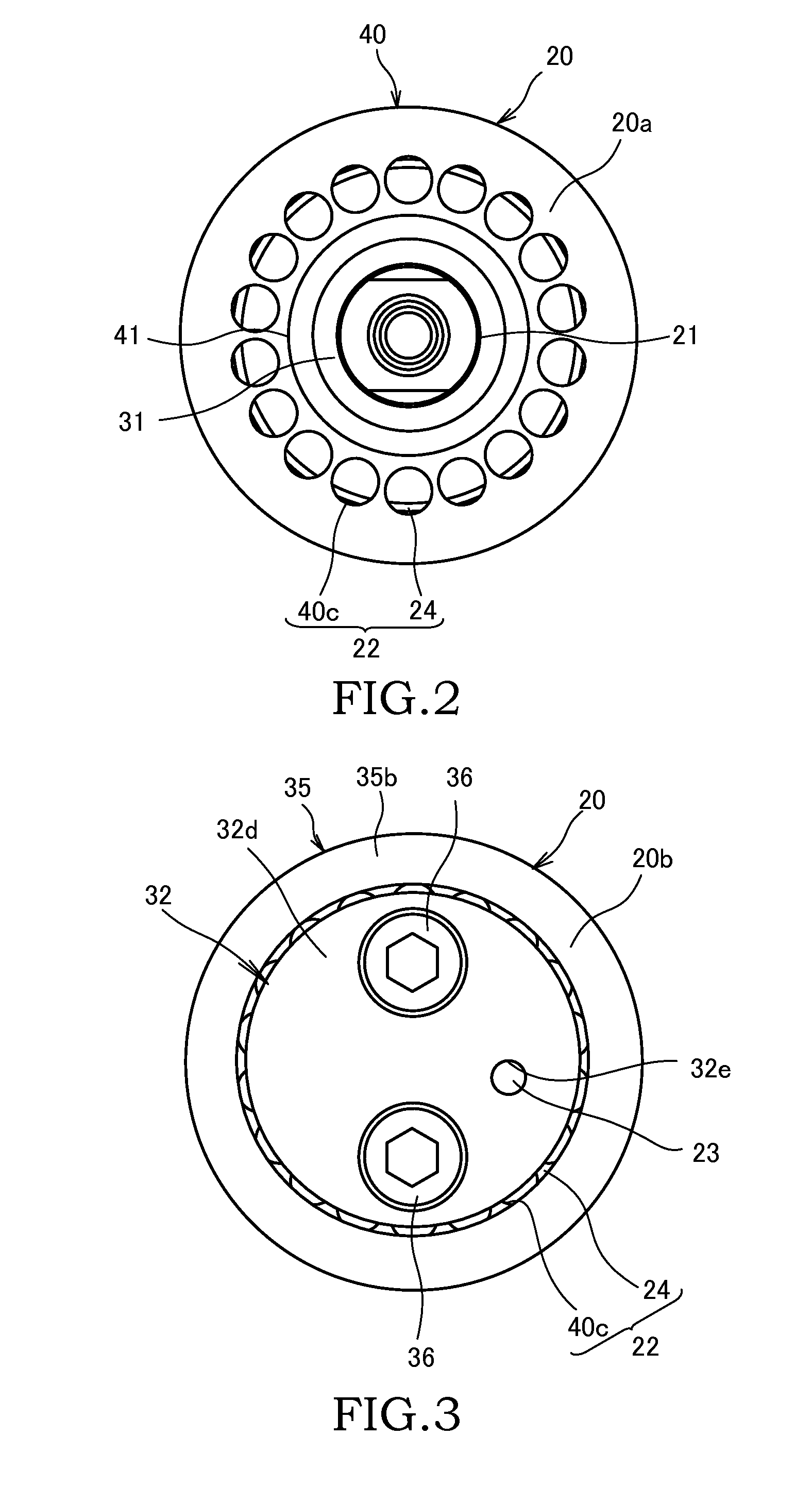
[0016]FIG. 1 is a sectional view showing a piston portion of a magnetorheological fluid damper (hereinafter, referred to merely as a “damper 1”). The damper 1 is interposed between a vehicle body and an axle in a vehicle such as an automotive vehicle and generates a damping force for suppressing vibration of the vehicle body by extending and contracting.

[0017]The damper 1 includes a hollow cylindrical cylinder 10 in which magnetorheological fluid is sealed as working fluid, a piston 20 which is slidably arranged in the cylinder 10 and partitions the interior of the cylinder 10 into first and second fluid chambers 11, 12, and a piston rod 21 which is coupled to the piston 20.

[0018]One end part 21a of the piston rod 21 is coupled to the piston 20 and another end part 21b thereof projects to the outside while being slidably inserted through a head portion (not shown) of the cylinder 10. The end part 21b of the piston rod 21 is coupled to one of the vehicle body and the ...

Example

Second Embodiment

[0067]Next, a magnetorheological fluid damper (hereinafter, referred to merely as a “damper 100”) according to a second embodiment of the present invention is described with reference to FIG. 4. The following description is centered on points of difference from the first embodiment and the same components as the damper 1 of the first embodiment are denoted by the same reference signs and not described.

[0068]In the damper 1 according to the first embodiment, the one end part 35a of the flux ring 35 is supported by the piston plate 40. In the damper 100 according to the second embodiment, a configuration in which both end parts 135a, 135b of a flux ring 135 are supported between a piston plate 80 and a piston plate 90 differs from the first embodiment.

[0069]A piston 120 includes a piston core 130 to which a piston rod 21 is coupled, the hollow cylindrical flux ring 135 for defining an annular main clearance 124 on the outer periphery of the piston core 130, and the pi...


PUM


Abstract

A magnetorheological fluid damper using magnetorheological fluid, whose viscosity changes according to an intensity of a magnetizing field, as working fluid includes a cylinder in which magnetorheological fluid is sealed, a piston which is slidably arranged in the cylinder, a first fluid chamber and a second fluid chamber which are partitioned by the piston, a main flow passage which is open on opposite end surfaces of the piston and allows communication between the first and second fluid chambers, an electromagnetic coil which generates a magnetizing field to be applied to the magnetorheological fluid flowing in the main flow passage, a bypass flow passage which is formed at a position less affected by the magnetizing field generated by the electromagnetic coil than the main flow passage, and a bypass branching portion which branches the bypass flow passage from the main flow passage.

Description

TECHNICAL FIELD[0001]The present invention relates to a magnetorheological fluid damper utilizing magnetorheological fluid whose viscosity changes by the action of a magnetizing field.BACKGROUND ART[0002]A magnetorheological fluid damper which changes a damping force by causing a magnetizing field to act on a flow passage in which magnetorheological fluid passes and changing an apparent viscosity of the magnetorheological fluid is known as a damper installed in a vehicle such as an automotive vehicle.[0003]JP2009-228861A discloses a magnetorheological fluid damper which changes a damping force by an electromagnetic force of an electromagnetic coil.[0004]This magnetorheological fluid damper includes first and second fluid chambers partitioned by a piston, a main flow passage (piston though passage) which is open on both ends of the piston and allows communication between the first and second fluid chambers, and a bypass flow passage which is open on the both ends of the piston and pa...

Claims


Application Information

Patent Timeline
IPC IPC(8): F16F9/53
CPCF16F9/535
Inventor SAITO, KEIJINAKAMURA, KAZUHISA
Owner KYB CORP
Why Eureka
Try Eureka