Brushless electric motor/generator

a brushless electric motor and generator technology, applied in the direction of rotating magnets, magnetic circuit rotating parts, synchronous machines with stationary armatures, etc., can solve the problems of low flux density, inability to produce sinusoidal output, and inability to produce a continuous output, etc., to achieve the effect of increasing the flux density

Inactive Publication Date: 2015-05-21
LINEAR LABS
View PDF2 Cites 41 Cited by
  • Summary
  • Abstract
  • Description
  • Claims
  • Application Information

AI Technical Summary

Benefits of technology

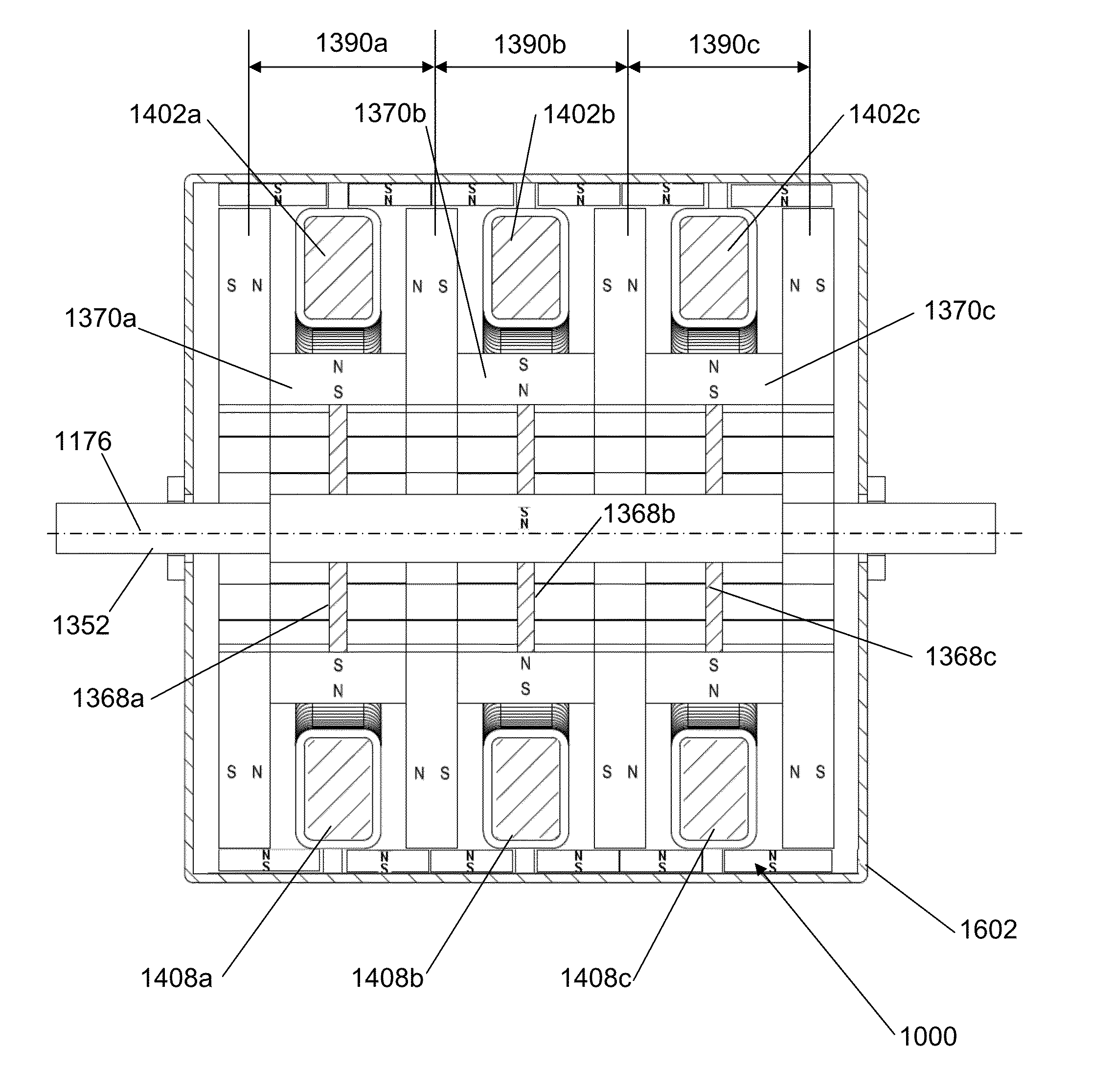
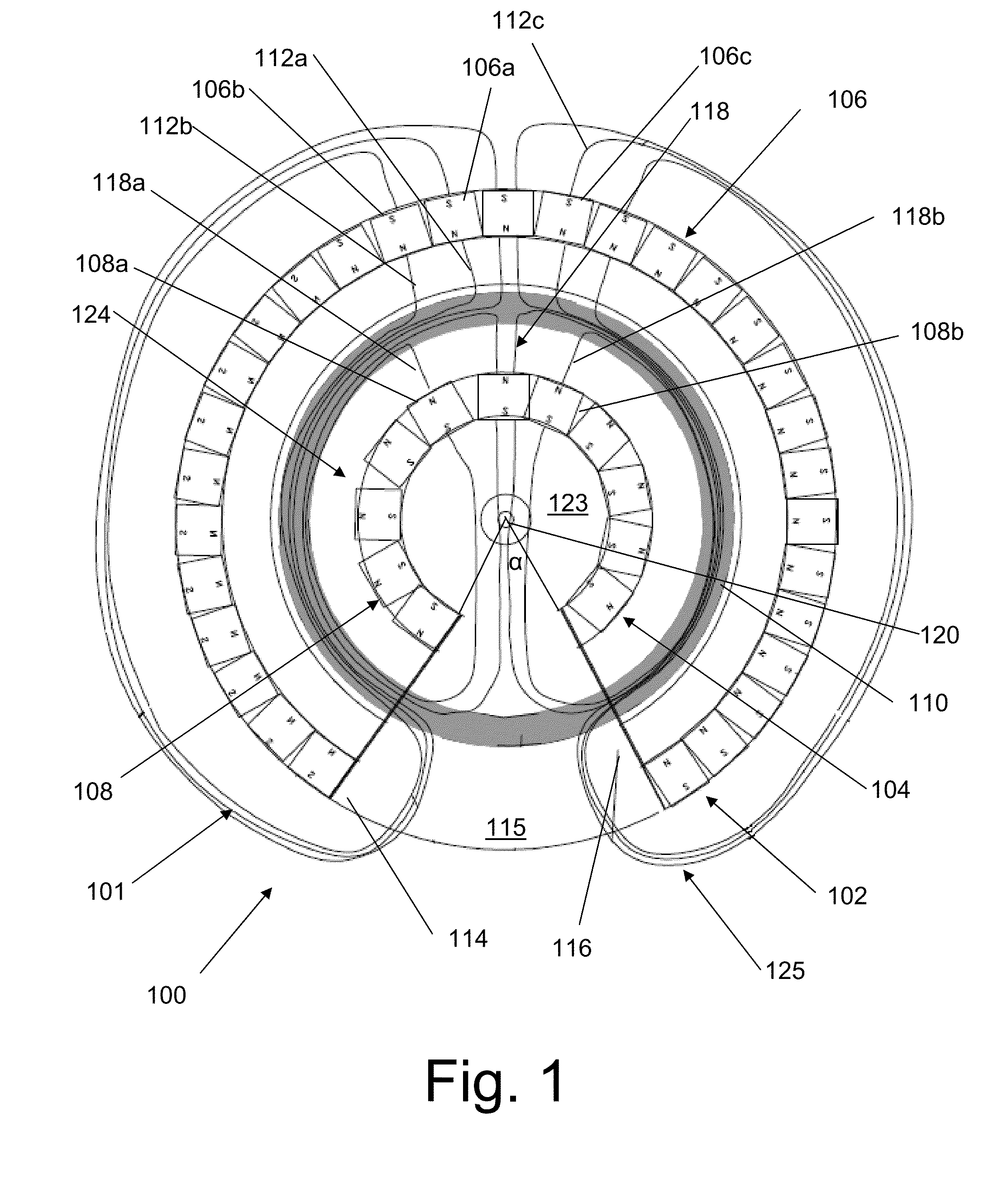
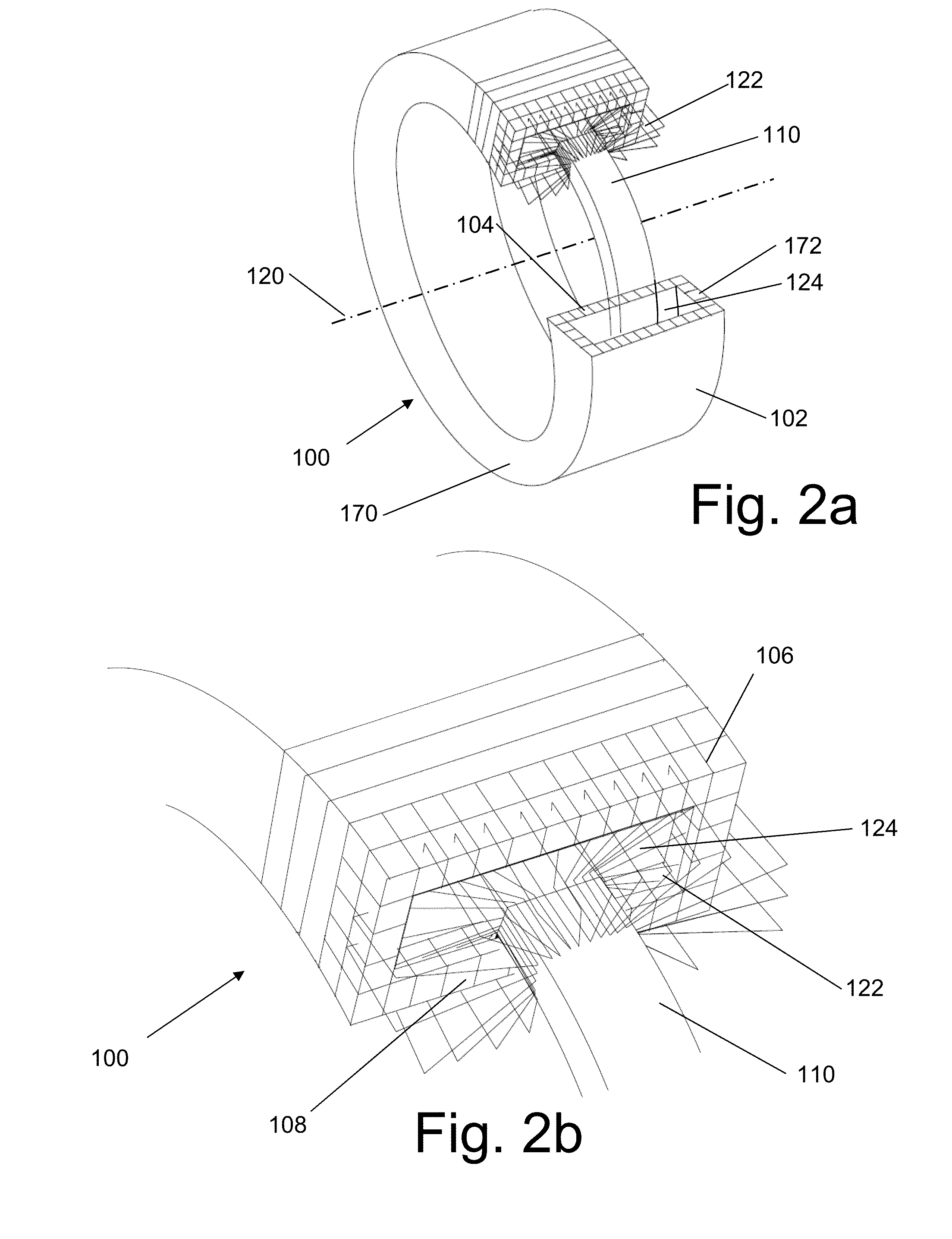
[0014]In response to these and other problems, there is presented various embodiments disclosed in this application, including methods and systems of increasing flux density by permanent magnet manipulation. Disclosed are various embodiments for a motor / generator comprising: a rotor adapted to rotate about a longitudinal axis, the rotor comprising a first partial toroidal magnetic cylinder defining a semi-circular tunnel, wherein the plurality of magnets forming the first partial toroidal magnetic cylinder have substantially all like poles facing inward toward the semi-circular tunnel, the semi-circular tunnel having an entrance and an exit forming an open throat defined by a space between the entrance and the exit, and a stator positioned about the longitudinal axis within a rotational path of the rotor.

Problems solved by technology

In fact, rotary generators are essentially very large quantities of wire spinning around the inside of very large magnets.
However output is a sinusoidal output which inherently has losses similar to that of conventional electric motors.
Specifically, the pulsed time varying magnetic fields produces undesired effects and losses, i.e. iron hysteresis losses, counter-EMF, inductive kickback, eddy currents, inrush currents, torque ripple, heat losses, cogging, brush losses, high wear in brushed designs, commutation losses and magnetic buffeting of permanent magnets.

Method used


Image

  • Brushless electric motor/generator
  • Brushless electric motor/generator
  • Brushless electric motor/generator

Examples


Embodiment Construction

[0034]Specific examples of components, signals, messages, protocols, and arrangements are described below to simplify the present disclosure. These are, of course, merely examples and are not intended to limit the invention from that described in the claims. Well-known elements are presented without detailed description in order not to obscure the present invention in unnecessary detail. For the most part, details unnecessary to obtain a complete understanding of the present invention have been omitted inasmuch as such details are within the skills of persons of ordinary skill in the relevant art. Details regarding conventional control circuitry, power supplies, or circuitry used to power certain components or elements described herein are omitted, as such details are within the skills of persons of ordinary skill in the relevant art.

[0035]When directions, such as upper, lower, top, bottom, clockwise, or counter-clockwise are discussed in this disclosure, such directions are meant t...


PUM


Abstract

Disclosed are various embodiments for a motor/generator comprising: a rotor adapted to rotate about a longitudinal axis, the rotor comprising a first partial toroidal magnetic cylinder defining a semi-circular tunnel, wherein the plurality of magnets forming the first partial toroidal magnetic cylinder have substantially all like poles facing inward toward the semi-circular tunnel, the semi-circular tunnel having an entrance and an exit forming an open throat defined by a space between the entrance and the exit, and a stator positioned about the longitudinal axis within a rotational path of the rotor.

Description

RELATED APPLICATIONS[0001]This application claims the benefit of the filing date of U.S. provisional patent application Ser. No. 62 / 055,615, entitled “An Improved DC Electric Motor / Generator with Enhanced Permanent Magnetic Flux Densities,” filed on Sep. 25, 2014, the disclosure of which is incorporated herein by reference for all purposes. This application also claims the benefit of the filing date of U.S. provisional patent application Ser. No. 62 / 056,389, entitled “An Improved DC Electric Motor / Generator with Enhanced Permanent Magnetic Flux Densities,” filed on Sep. 26, 2014, the disclosure of which is incorporated herein by reference for all purposes. This application is also a continuation-in-part of the commonly owned U.S. application Ser. No. 13 / 848,048, entitled “An Improved DC Electric Motor / Generator with Enhanced Permanent Magnetic Flux Densities” filed on Mar. 20, 2013, which claims the benefit of U.S. Provisional Application Ser. No. 61 / 613,022, filed on Mar. 20, 2012,...

Claims


Application Information

Patent Timeline
Patent Type & Authority Applications(United States)
IPC IPC(8): H02K1/27H02K3/04H02K1/30
CPCH02K1/27H02K3/04H02K1/30H02K21/12H02K1/2791H02K1/12H02K21/22
Inventor HUNSTABLE, FRED E.
Owner LINEAR LABS
Why Eureka
Try Eureka