Thin-film magnetic head, method of manufacturing the same, head gimbal assembly and hard disk drive

a technology of magnetic head and gimbal, which is applied in the direction of data recording, instruments, and heads with metal sheet cores, can solve the problems of adversely affecting the detection of servo signals, or the s/n ratio of reproduction waveforms, so as to reduce the magnetostriction , improve the recording density, and avoid the effect of impairment of overwriting characteristics

Active Publication Date: 2005-12-22
HEADWAY TECH INC
View PDF25 Cites 28 Cited by
  • Summary
  • Abstract
  • Description
  • Claims
  • Application Information

AI Technical Summary

Benefits of technology

[0015] In the case of a conventional PMR other than a thin-film magnetic head 400, the main pole layer is preferably a magnetic material with a small maximum coercivity Hc (about 2-10 Oe) and a small magnetostriction λ (1−3×10⁻⁶), while it is also preferably a magnetic material with a small magnetostriction λ in order to eliminate the aforementioned pole erasure.
[0016] However, in order to avoid impairment in the overwrite characteristic which occurs with flux saturation even if the track width is narrowed to improve the recording density, the magnetic material of the main pole layer 402 is preferably formed of a magnetic material with a high saturated flux density, but when this is done it becomes difficult to lower the magnetostriction λ of the main pole layer 402. Consequently, with conventional PMRs such as a thin-film magnetic head 400, it has been difficult to both achieve improved recording density and prevent pole erasure. For this reason, it has been a goal to modify the structure of conventional PMRs to prevent appearance of pole erasure while improving recording density.
[0017] It is an object of the present invention, which has been accomplished in light of the problems described above, to provide a thin-film magnetic head having a structure which allows the recording density to be improved while preventing appearance of pole erasure, as well as a method of manufacturing the same, a head gimbal assembly and a hard disk drive.
[0024] This will allow the saturated flux density of the magnetic pole tip to be higher, to avoid saturation of the flux even when the track width of the magnetic pole tip is narrowed.
[0051] By carrying out each of these steps, it is possible to obtain a thin-film magnetic head wherein the main pole layer has a joined structure in which the main pole layer and the yoke pole section with a larger size than the magnetic pole tip are joined.
[0053] By carrying out annealing, it is possible to reduce the effect of remnant magnetization inside the magnetic pole tip after completion of writing.

Problems solved by technology

When the writing performance is high with a perpendicular recording type magnetic head (perpendicular magnetic recording head: hereinafter also referred to as “PMR”), this skew angle is responsible for a problem of side fringe, whereby excess data is recorded between adjacent tracks.
When side fringe occurs, it can adversely affect detection of the servo signal, or the S / N ratio of the reproduction waveform.

Method used


Image

  • Thin-film magnetic head, method of manufacturing the same, head gimbal assembly and hard disk drive
  • Thin-film magnetic head, method of manufacturing the same, head gimbal assembly and hard disk drive
  • Thin-film magnetic head, method of manufacturing the same, head gimbal assembly and hard disk drive

Examples


first embodiment

(Structure of thin-film magnetic head)

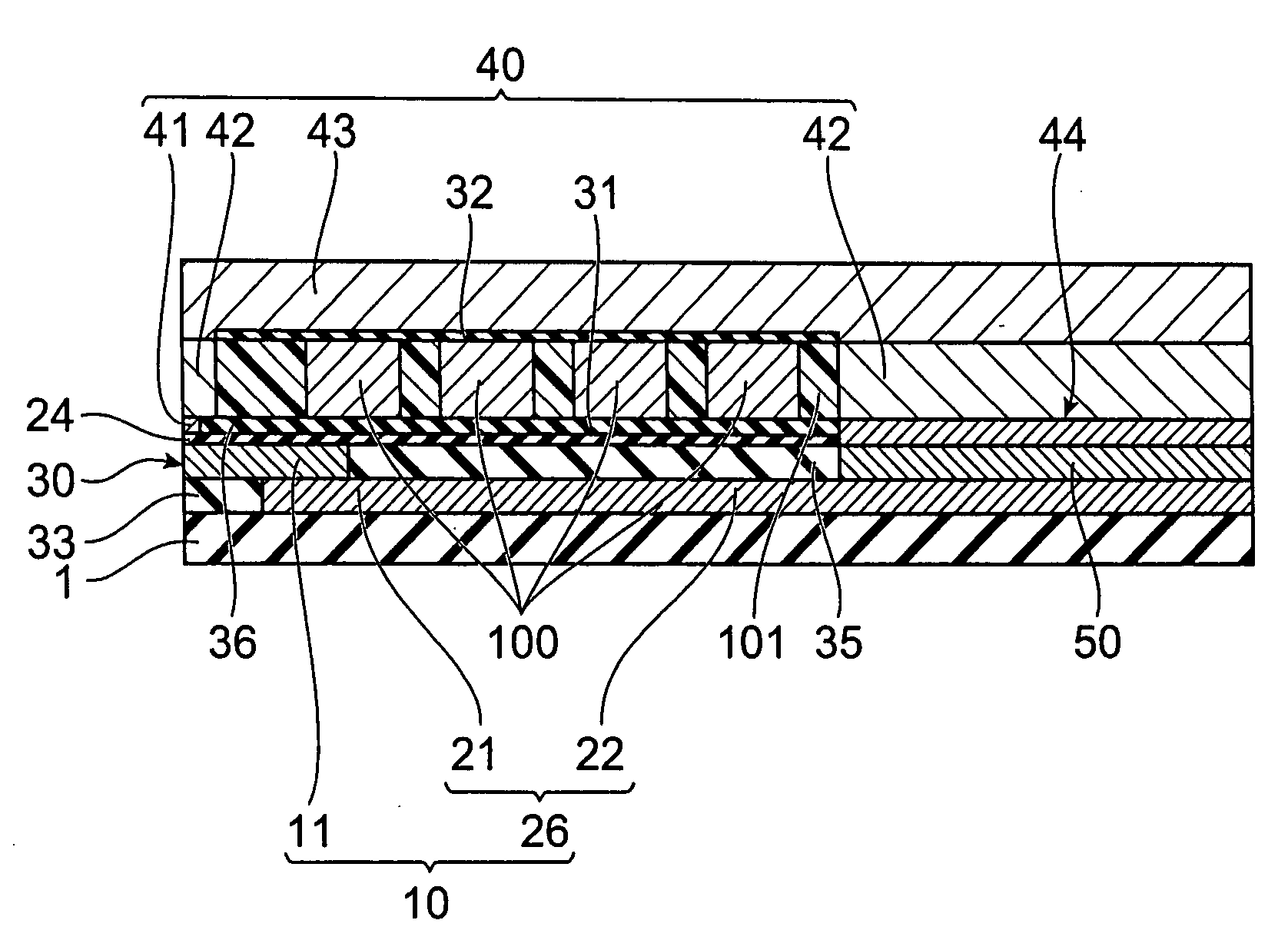
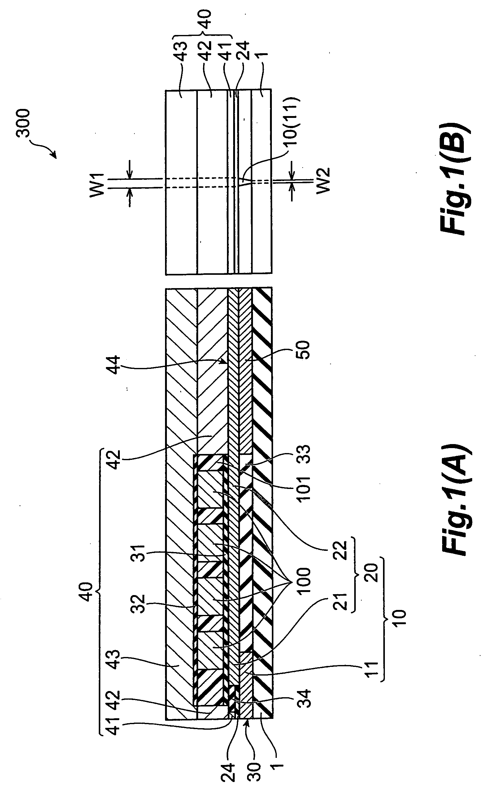
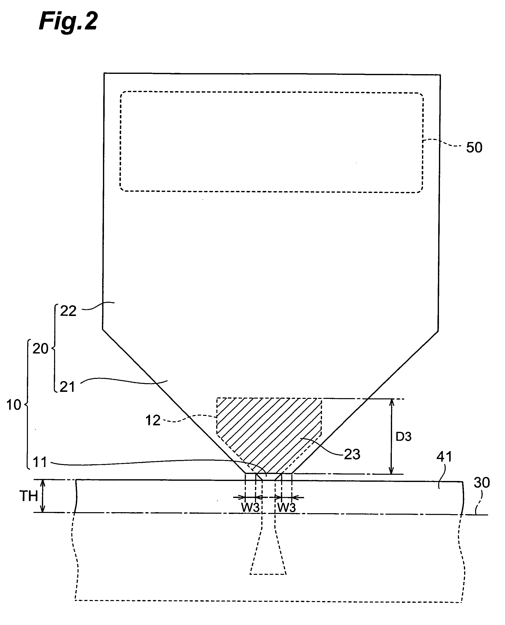
[0089] The structure of a thin-film magnetic head according to the first embodiment of the invention will be explained first, with reference to FIGS. 1 to 4. FIG. 1(A) is a cross-sectional view of a thin-film magnetic head 300 according to a first embodiment of the invention, in the direction crossing the thin-film coil, and FIG. 1(B) is a front view showing the ABS, FIG. 2 is a plan view showing the main pole layer 10 and first shield section 41 of the thin-film magnetic head 300, FIG. 3 is a plan view showing the main pole layer 10 with the direction of internal magnetization, and FIG. 4 is a perspective view showing the joint section of the magnetic pole tip 11 and upper yoke pole section 20 of the main pole layer 10.

[0090] The thin-film magnetic head 300 according to the first embodiment is a perpendicular recording type magnetic head having an ABS 30 as the medium-opposing surface opposite the recording medium (hard disk), and it compris...

second embodiment

[0131] A thin-film magnetic head according to a second embodiment of the invention will now be explained with reference to FIGS. 10(A), (B). FIG. 10(A) is a cross-sectional view of the thin-film magnetic head 310 according to the second embodiment of the invention, in the direction crossing the thin-film coil, and FIG. 10(B) is a front view showing the ABS.

(Structure of Thin-Film Magnetic Head)

[0132] The thin-film magnetic head 310 according to the second embodiment of the invention differs from the thin-film magnetic head 300 described above primarily in that the main pole layer 10 has a lower yoke pole section 26 instead of an upper yoke pole section 20. It also differs in that it has insulating films 35,36 instead of insulating films 31,34, and in that the shape of the write shield layer 40 is different, but is the same in its other aspects. The differences will now be explained, ignoring the aspects which are identical.

[0133] The main pole layer 10 in the thin-film magnetic ...

modification example 1

(Modification Example 1)

[0136] The thin-film magnetic head 310 may also have a tensile film 52 between the insulating layer 1 and the lower yoke pole section 26, as shown in FIGS. 21(A) and (B). The tensile film 52 is the same high tensile strength film as the tensile film 51, made of the same material as the tensile film 51. The lower yoke pole section 26 has a larger size than the magnetic pole tip 11, and therefore the magnetic charge of the lower yoke pole section 26 is larger than the magnetic charge of the magnetic pole tip 11, and the effect of the remnant magnetization of the lower yoke pole section 26 is that much more notable in the thin-film magnetic head 310. However, by providing the tensile film 52 it is possible to maintain the direction of remnant magnetization mr of the lower yoke pole section 26 after completion of writing in the direction along the ABS 30, to allow appearance of pole erasure to be effectively prevented.

[0137] Incidentally, though not shown in thi...


PUM

PropertyMeasurementUnit
coercivity Hcaaaaaaaaaa
heightaaaaaaaaaa
depth D3aaaaaaaaaa

Abstract

A thin-film magnetic head has a laminated construction comprising a main pole layer having a magnetic pole tip on the side of the medium-opposing surface opposing a recording medium, a write shield layer opposite the magnetic pole tip forming a recording gap layer, on the side of the medium-opposing surface, and a thin-film coil wound around at least a portion of the write shield layer. The main pole layer has the magnetic pole tip with a shortened structure which is not connected to the write shield layer, and an upper yoke pole section and / or lower yoke pole section with a larger size than the magnetic pole tip, and has a joined structure wherein the upper yoke pole section and / or lower yoke pole section is joined to the magnetic pole tip.

Description

CROSS REFERENCE TO RELATED APPLICATIONS [0001] This application claims priority to Provisional Application No. 60 / 580,368, filed on Jun. 18, 2004, which is hereby incorporated by reference in its entirety.BACKGROUND OF THE INVENTION [0002] 1. Field of the Invention [0003] The present invention relates to a thin-film magnetic head which performs magnetic recording operation by a perpendicular recording system, a method of manufacturing the same, a head gimbal assembly and hard disk drive. [0004] 2. Related Background Art [0005] Surface recording densities in hard disk drives have improved dramatically in recent years. More particularly, surface recording densities in hard disk drives have recently reached 160-200 Gbytes / platter, and are poised to exceed even this level. At the same time, there has been a demand for improved performance of thin-film magnetic heads. [0006] Thin-film magnetic heads are largely classified based on their recording systems, which may be divided into longit...

Claims


Application Information

Patent Timeline
Patent Type & Authority Applications(United States)
IPC IPC(8): G11B5/127G11B5/147G11B5/187G11B5/31
CPCG11B5/1278G11B5/1872G11B5/3163G11B5/3143G11B5/3103
Inventor SASAKI, YOSHITAKAGUAN, LIJIEITO, HIROYUKI
Owner HEADWAY TECH INC
Why Eureka
Try Eureka