
Protection case

Inactive Publication Date: 2015-05-21
JWIN ELECTRONICS
View PDF8 Cites 34 Cited by
  • Summary
  • Abstract
  • Description
  • Claims
  • Application Information

AI Technical Summary

Benefits of technology

The present disclosure provides different protective cases for wearable electronic devices. The cases protect and waterproof the devices, while also allowing for easy coupling and separation. The cases can be designed with an auxiliary battery cell attached or detached from the device, or a separate battery can be added. Additionally, the cases can include a solar cell module to generate power from sunlight and provide it to the device without the need for a separate battery cell. The cases can also be designed with a soft band or rotatable part, making them more comfortable and user-friendly. Overall, the disclosure provides improved protection and more convenient access for wearable electronic devices.

Problems solved by technology

Such a portable electronic device is specially processed through coating to protect an outer surface thereof from an external environment, but cannot be protected from everyday damages, foreign substances, and water.
Although the wearable electronic device can improve portability and prevent a danger of loss as it is put on the body or a wrist of a user, it may collide with another external object and may be easily damaged due to an impact while the user does not recognize the fact when the user moves with the wearable electronic device being put on the body of the user, and is always exposed to an external environment.
Thus, water may be introduced into the wearable electronic device and the product may break.
However, according to the conventional wearable electronic device, when the electric power of the battery pack and the spare battery pack are exhausted, another battery back should be mounted to the electronic device.
Further, due to the limited battery capacity, a process of executing various functions is often inconvenient.

Method used


Image

  • Protection case
  • Protection case
  • Protection case

Examples


first embodiment

Here, first, among the embodiments of the present disclosure, a protection case of a wearable electronic device according to the present disclosure will be described.

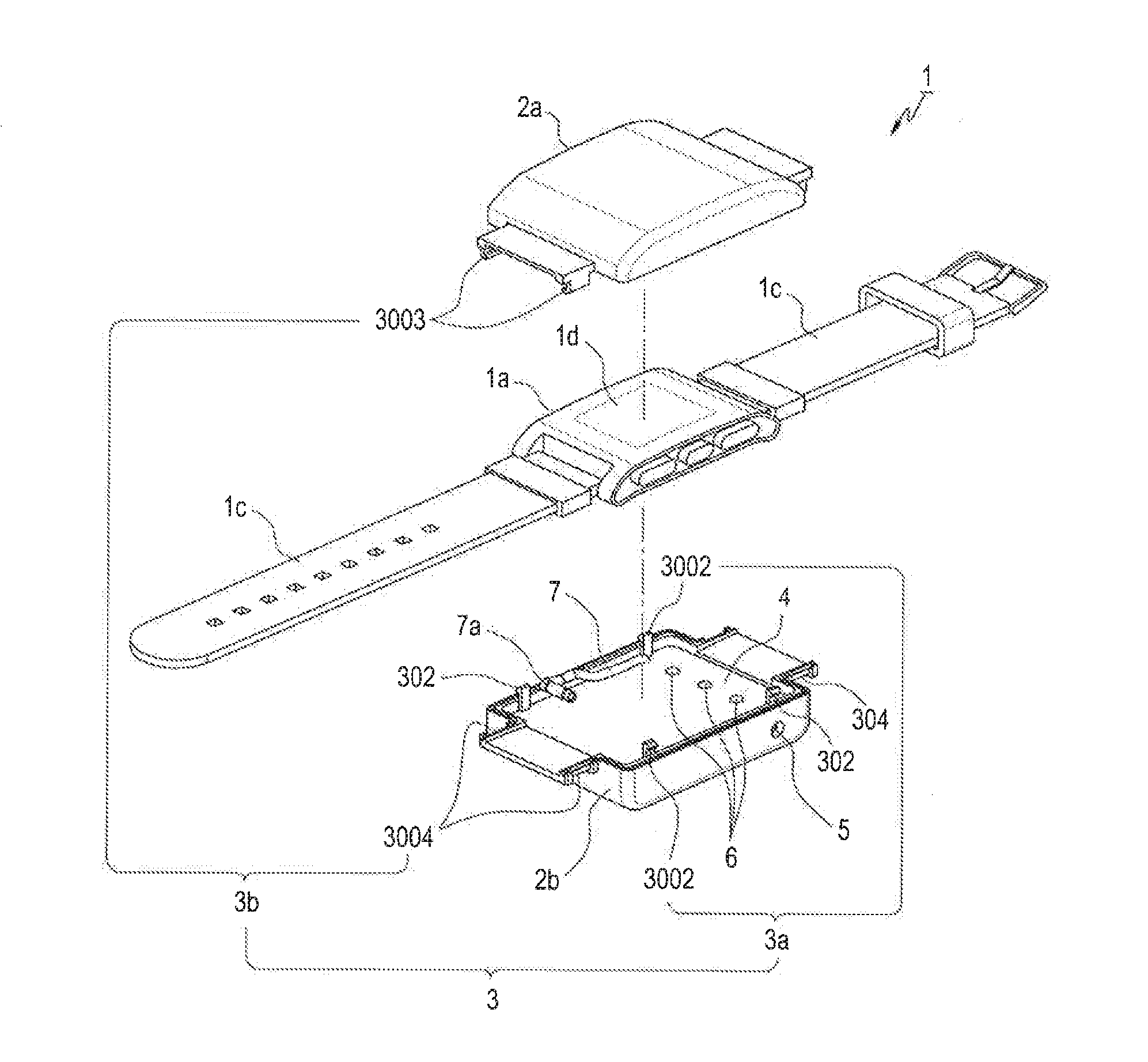
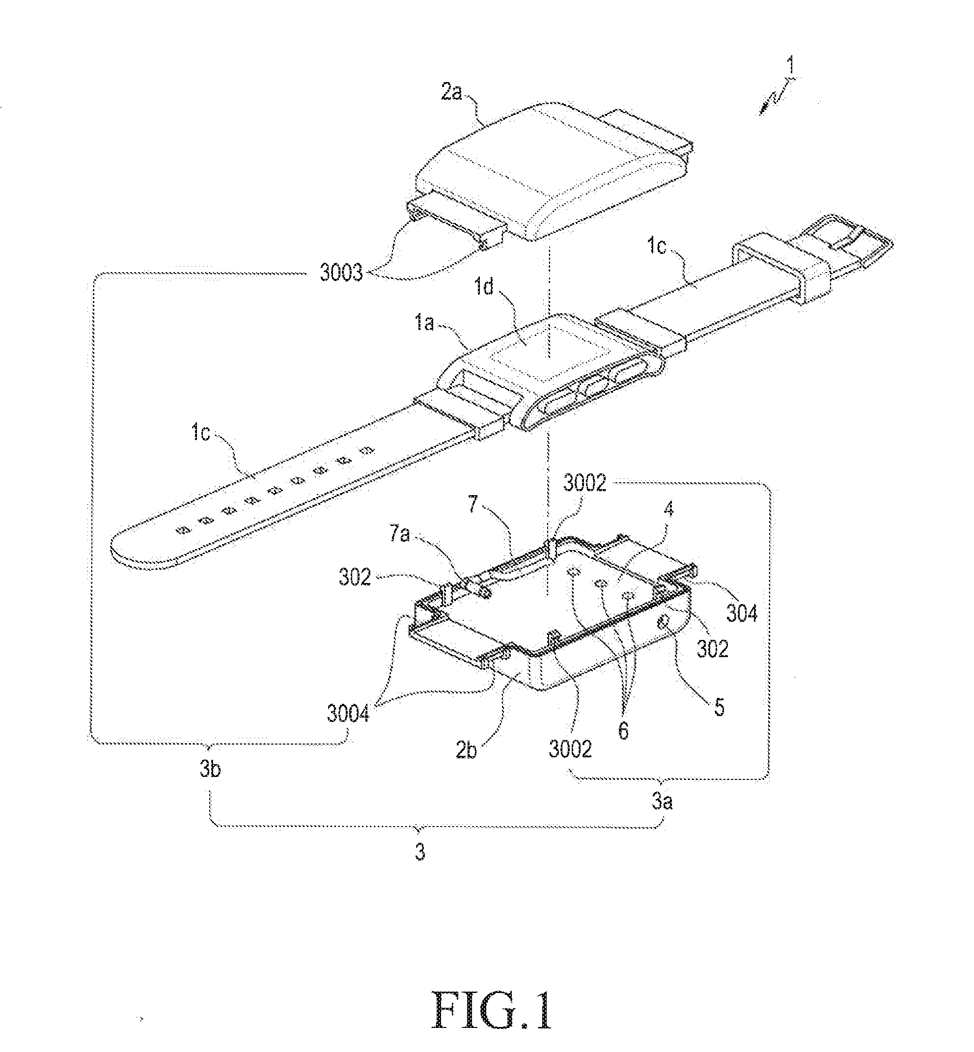
FIG. 1 is an exploded perspective view illustrating a configuration of a protection case according to a first embodiment of the present disclosure. FIG. 2 is a cutaway perspective view illustrating a second case of the protection case according to the first embodiment of the present disclosure.

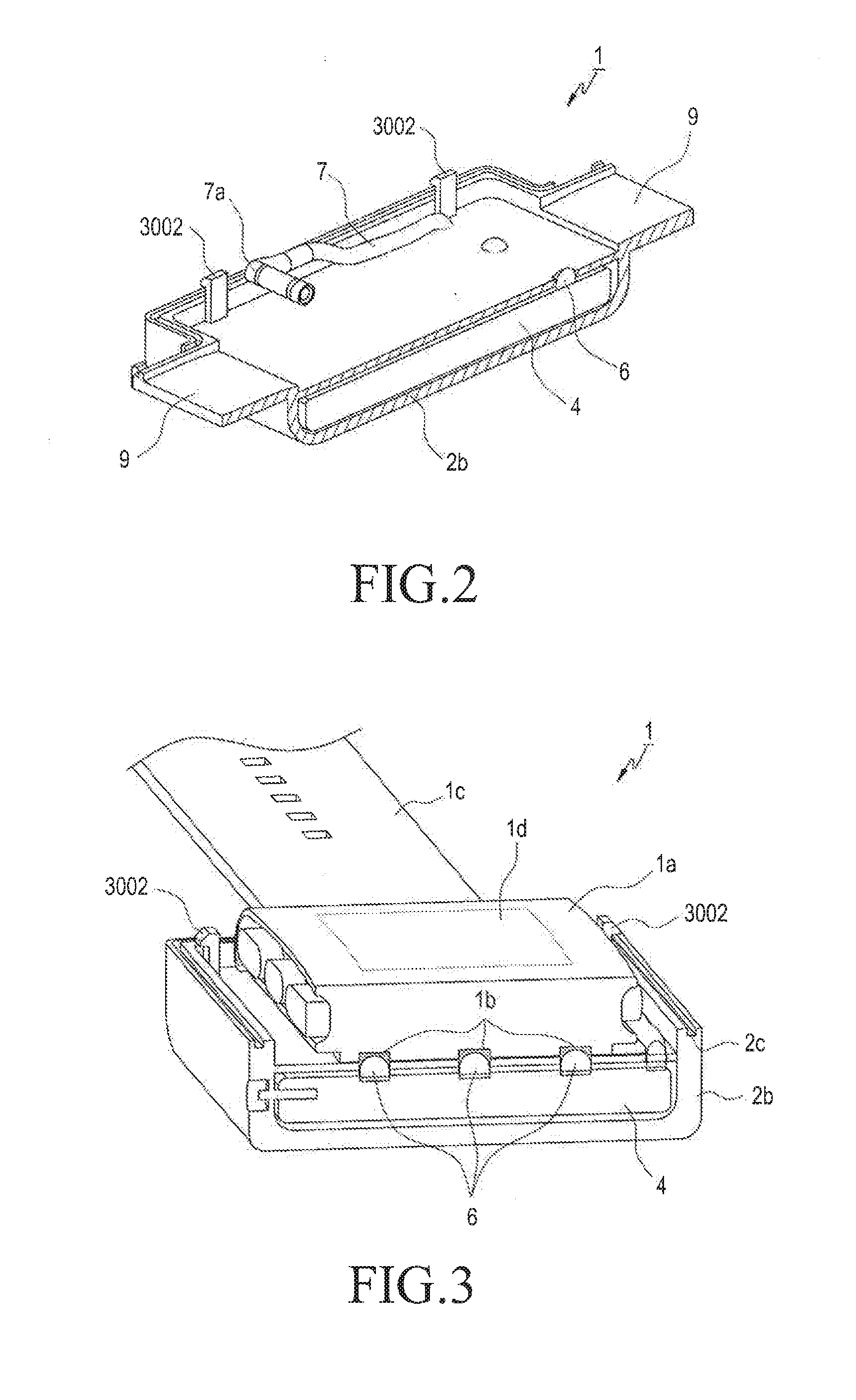
Referring to FIGS. 1 and 2, the protection case 1 includes a protection case body 2 including first and second cases 2a and 2b, and one or more coupling parts 3. The coupling parts 3 couple the first and second cases 2a and 2b and enclose the wearable electronic device 1a when the coupling parts 3 are coupled to each other, and allow the first and second cases 2a and 2b to be separated from each other and the wearable electronic device 1a to be removed when the coupling parts 3 are separated from each other.

In this way, since the ...

second embodiment

Hereinafter, a protection case of a wearable electronic device according to the present disclosure will be described with reference to the accompanying drawings.

FIG. 9 is an exploded perspective view illustrating a configuration of a protection case according to a second embodiment of the present disclosure. FIG. 10 is a perspective view illustrating a state before an operation of the protection case according to the second embodiment of the present disclosure. FIG. 11 is a perspective view illustrating an operation of the protection case according to the second embodiment of the present disclosure.

Referring to FIGS. 9 to 11, the protection case 10 includes a protection case body 20, a case 30 in which an auxiliary battery cell 40 (see FIG. 12) is embedded, and a wearing part 40. An opening 21 is formed at a lower portion of the protection case body 20 so that the case 30 can be introduced or extracted through the opening 21. As the wearable electronic device 1a is slid, the protect...

third embodiment

Hereinafter, a protection case according to the present disclosure will be described with reference to the accompanying drawings.

FIG. 16 illustrates exploded perspective views illustrating a protection case according to a third embodiment of the present disclosure. FIG. 17 is a perspective view illustrating a coupled state of the protection case according to the third embodiment of the present disclosure. FIG. 18 is a side sectional view illustrating a coupled state of the protection case according to the third embodiment of the present disclosure.

Referring to FIGS. 16 to 18, the protection case 100 includes a case body in which an auxiliary battery cell 40 is embedded, a protection case 120, and a wearing part 130. The case body 110 may be electrically connected to the wearable electronic device 1a and supply electric power to the wearable electronic device 1a. That is, since a positioning part 110a for coupling the wearable electronic device 1a and positioning the wearable electro...


PUM


Abstract

A protection case for protecting a wearable electronic device includes: a protection case body that comprises first and second cases; and one or more coupling parts that are provided in the protection case body. The coupling parts couple the first and second cases to each other and couple the wearable electronic device while enclosing the wearable electronic device when the coupling parts are coupled to each other, and separate the first and second cases from each other and separate the wearable electronic device when the coupling parts are separated from each other.

Description

TECHNICAL FIELDThe present disclosure relates to a protection case for protecting and waterproofing a wearable electronic device.RELATED ARTIn recent years, various electronic devices are provided to users, and portable electronic devices, such as portable terminals, MP3 players, Portable Multimedia Players (PMPs), and electronic books, that allows users to access various contents while the users carry them have been widely used.Such a portable electronic device is specially processed through coating to protect an outer surface thereof from an external environment, but cannot be protected from everyday damages, foreign substances, and water.Recently, a wearable electronic device put on the body or a wrist of a user or clothes has been developed.Although the wearable electronic device can improve portability and prevent a danger of loss as it is put on the body or a wrist of a user, it may collide with another external object and may be easily damaged due to an impact while the user ...

Claims


Application Information

Patent Timeline
IPC IPC(8): H05K5/02A45F5/00H02J7/00H05K5/06H02J7/35
CPCH05K5/0217H05K5/069A45F2005/008H02J7/0047A45F5/00H02J7/355A45F2005/002A45F2200/0508A45F2200/0516G04B37/084G04B37/1486G04G17/083H02J7/342H02J7/35H02J7/0048
Inventor KIM, JUSTIN CHIWON
Owner JWIN ELECTRONICS
Learn More