Power generation/transmission device

Inactive Publication Date: 2015-05-28
YAMAMOTO KAZUE
View PDF2 Cites 1 Cited by
  • Summary
  • Abstract
  • Description
  • Claims
  • Application Information

AI Technical Summary

Benefits of technology

The invention allows for the rotation of a drive rotating disc by using the rising and falling motion of drive rods and the rolling motion of a spherical body. This creates a stable power output by combining the motion of the drive rods and the spherical body.

Problems solved by technology

In recent years, many problems such as influence of earthquake disaster and depletion of fuel are coming to the surface.
However, utilization of the natural energy has difficulty in obtaining stable and inexpensive electric energy.

Method used


Image

  • Power generation/transmission device
  • Power generation/transmission device
  • Power generation/transmission device

Examples


second embodiment

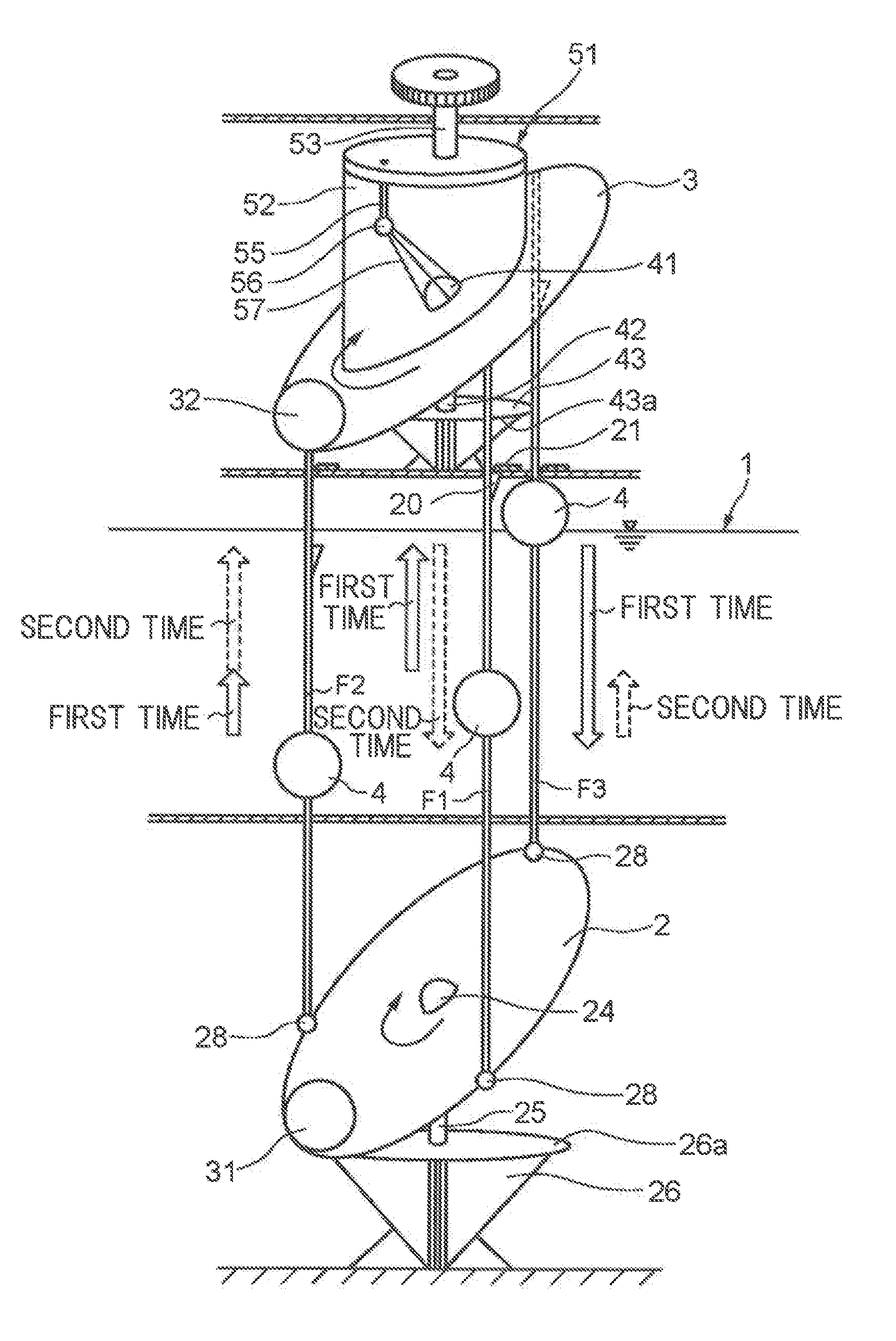
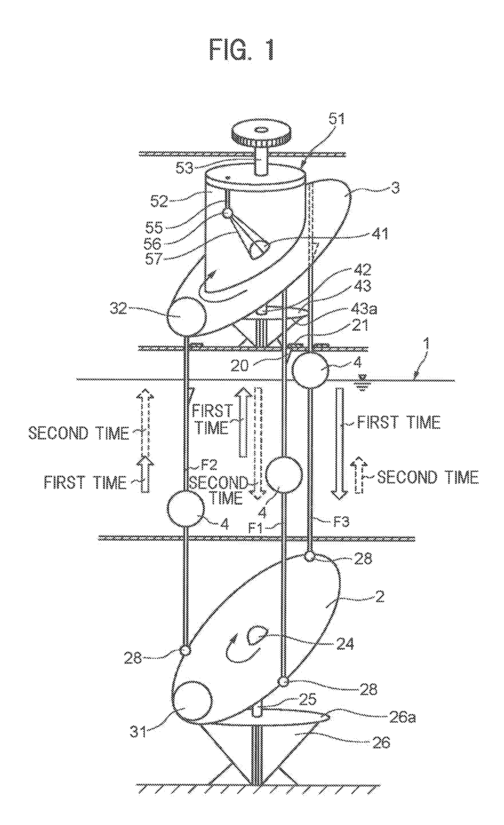
[0046]In the power generation / transmission device in the second embodiment, the drive rotating disc 101 is formed by two discs, i.e., a spherical body rolling disc 101b and a spherical body housing disc 101a (refer to FIG. 9). The special rotating disc 102 is formed by two discs, i.e., a spherical body rolling disc 102b and a spherical body housing disc 102a similarly to the drive rotating disc 101 (refer to FIG. 11).

[0047]FIG. 9 illustrates a detailed view of the drive rotating disc 101. In FIG. 9, only a left half of the drive rotating disc 101 is illustrated and a right half thereof is omitted. The drive rotating disc 101 includes the doughnut-shaped spherical body rolling disc 101b on which a first spherical body 32 is placed for rolling motion and the spherical body housing disc101a for rotating about a first universal joint 41 relative to the spherical body rolling disc 101b. The spherical body rolling disc 101b and the spherical body housing disc 101a are parallel to each oth...

first embodiment

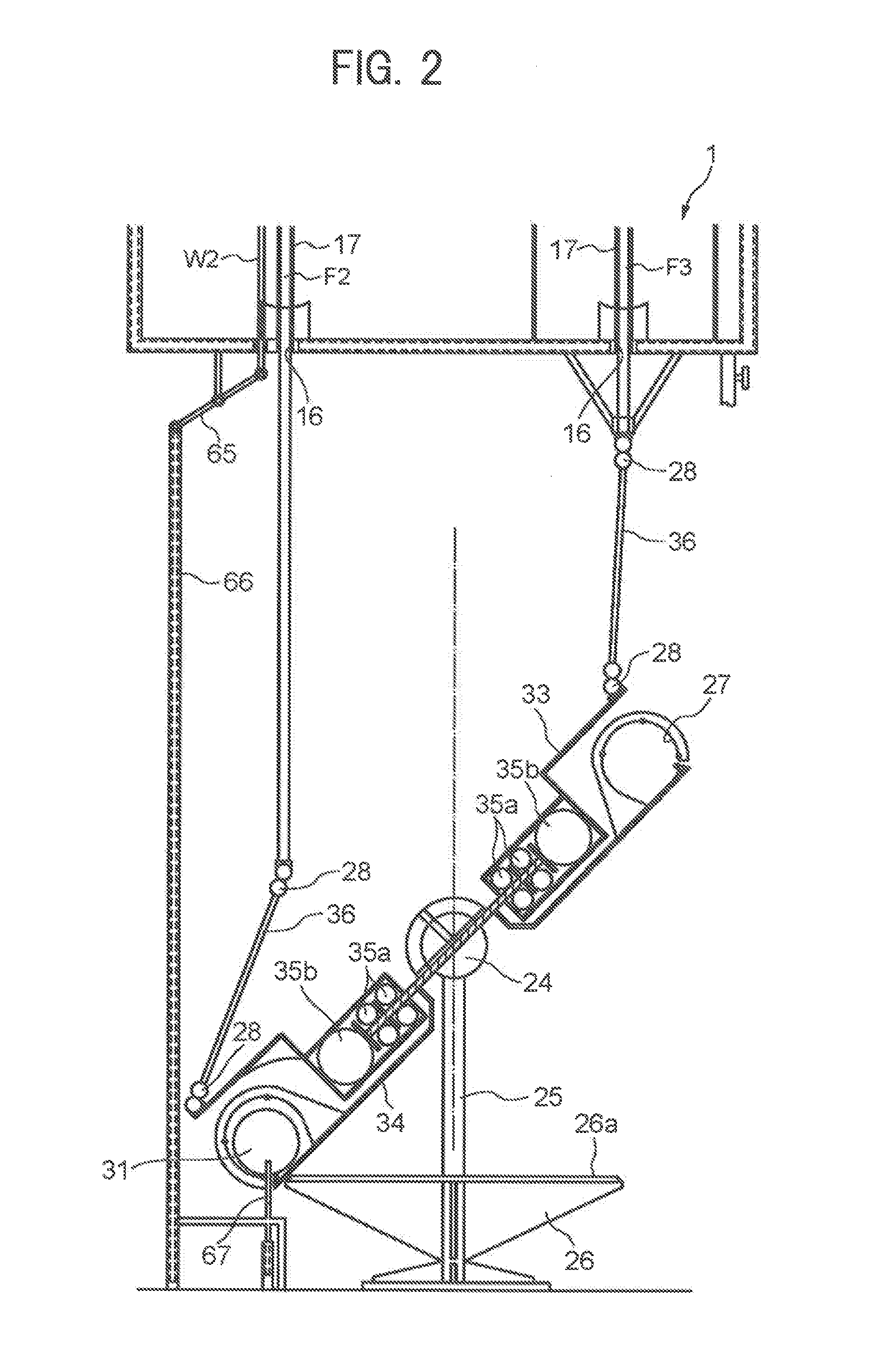
[0060]The invention is not limited to the embodied forms in the above-described embodiments but can be changed into various embodiments without changing the gist of the invention. For example, in the power generation / transmission device in the invention, as means of lifting and lowering the vertical moving rods, it is possible to use feed screw mechanisms using fuel, electric energy, air pressure, or the like as a drive source or pneumatic cylinders or hydraulic cylinders besides the buoyancy of the liquid.

[0061]It is only necessary for the drive rotating disc to be placed on the upper ends of the vertical moving rods to be slidable in the circumferential direction. For example, upper ends of vertical moving rods and a drive rotating disc may be connected with spherical bearings and circular arc guide devices interposed therebetween.

[0062]The present description is based on Japanese Patent Application No. 2012-131287 filed on Jun. 8, 2012 and Japanese Patent Application No. 2012-216...


PUM


Abstract

Provided is a power generation / transmission device capable of obtaining stable power by utilizing rising and falling motion of rods and rolling motion of a spherical body. The power generation / transmission device includes: drive rods F1 to F3 capable of rising and falling in a vertical direction; a drive rotating disc 3 supported to be three-dimensionally rotatable about a first universal joint 41 to rotate on a conical trajectory along a circular track of a first angle restricting plate 43 disposed below the drive rotating disc 3; and a first spherical body 32 placed on the drive rotating disc 3 to be capable of rolling motion. The drive rotating disc 3 is rotated by the rising and falling motion of the drive rods F1 to F3 and the rolling motion of the first spherical body 32.

Description

TECHNICAL FIELD[0001]The present invention relates to a power generation / transmission device for generating and transmitting power by utilizing rising and falling motion of rods and rolling motion of a spherical body.BACKGROUND ART[0002]As conventional electric power generation methods, thermal electric power generation in which reaction heat energy of fuel such as petroleum and natural gas is converted into electric power, and nuclear electric power generation utilizing nuclear power are known. In the thermal electric power generation and the nuclear electric power generation, heat energy is generated artificially or chemically and the heat energy is converted into electric energy. In recent years, many problems such as influence of earthquake disaster and depletion of fuel are coming to the surface.[0003]Instead of utilizing the nuclear power and the thermal power, research and development of electric power generation utilizing natural energy such as wind power and sunlight are ad...

Claims


Application Information

Patent Timeline
IPC IPC(8): F03B17/02F03B17/04F16H23/08
CPCF03B17/025F03B17/04F16H23/08Y02E10/20Y02E10/30F16H23/04
Inventor AZEGAMI, NORIO
Owner YAMAMOTO KAZUE
Why Eureka
Try Eureka