Breathing system for internal combustion engines, using dual duty (alternatively exhaust-intake) valves and a forced air supply

Inactive Publication Date: 2001-09-25
DE FRANCISCO ROBERTO FORERO
View PDF8 Cites 8 Cited by
  • Summary
  • Abstract
  • Description
  • Claims
  • Application Information

AI Technical Summary

Benefits of technology

Furthermore, the pressure losses during the intake process also reduce the unit air charge (weight or mass of air drawn into the cylinder per intake stroke) and therefore less fuel can be burned effectively in the combustion process. Consequently, this smaller unit air charge also reduces the thermal energy delivered by the combustion process in each cycle and therefore decreases the effective power delivered by the engine For this reason actual engines usually have intake valves of larger size than exhaust valves, since intake pressure losses have greater negative effects than exhaust pressure losses.
It is worthy of note that although the system of the invention makes use of a fan (or blower or compressor), as some supercharged engines do, it differs from this system. While the purpose of the supercharged is to overcome the fluid friction pressure losses during the intake process, in order to increase the unit air charge, at the expense of work and power which must be delivered by the engine to the supercharger, in the system of the invention such pressure losses are reduced (not overcome) both during the exhaust and the intake processes, obtaining a reduction of the negative work of the pistons and increasing the unit air charge.

Problems solved by technology

The effective (or brake) horsepower (bhp) that an internal combustion engine can deliver is limited to a great extent by the fluid friction losses, or pressure losses, generated both during exhaust of combustion gases from the cylinder (through the exhaust valves) and intake of air to the cylinder (through the intake valves).
Such pressure losses increase the mean effective pressure that the piston has to overcome both during the exhaust stroke and the intake stroke, resulting in work being wasted in each cycle and consequently in less useful effective power being delivered by the engine.
Furthermore, the pressure losses during the intake process also reduce the unit air charge (weight or mass of air drawn into the cylinder per intake stroke) and therefore less fuel can be burned effectively in the combustion process.
Consequently, this smaller unit air charge also reduces the thermal energy delivered by the combustion process in each cycle and therefore decreases the effective power delivered by the engine For this reason actual engines usually have intake valves of larger size than exhaust valves, since intake pressure losses have greater negative effects than exhaust pressure losses.
For this reason, it is desirable to increase as much as is possible the valve opening area in order to obtain a greater power output (bhp) from a given engine However, the space available to accomodate the valves is limited and it is not possible to enlarge the valve opening area by either increasing the size or the number of valves per cylinder beyond a certain practical limit for a given size of engine.
This is however,accomplished at the expense of obtaining less work from the combustion gases during the power stroke.
However, this is accomplished at the expense of decreasing the effective compression stroke and therefore lowering the compression ratio, which in turn decreases the thermal efficiency of the cycle which is a function of the compression ratio.
As a consequence, the fuel consumption increases, especially at low speeds and high load (full throttle opening).
In present engines, the exhaust valves suffer greatly from overheating since they only handle the hot gases of combustion.

Method used


Image

  • Breathing system for internal combustion engines, using dual duty (alternatively exhaust-intake) valves and a forced air supply
  • Breathing system for internal combustion engines, using dual duty (alternatively exhaust-intake) valves and a forced air supply
  • Breathing system for internal combustion engines, using dual duty (alternatively exhaust-intake) valves and a forced air supply

Examples


Embodiment Construction

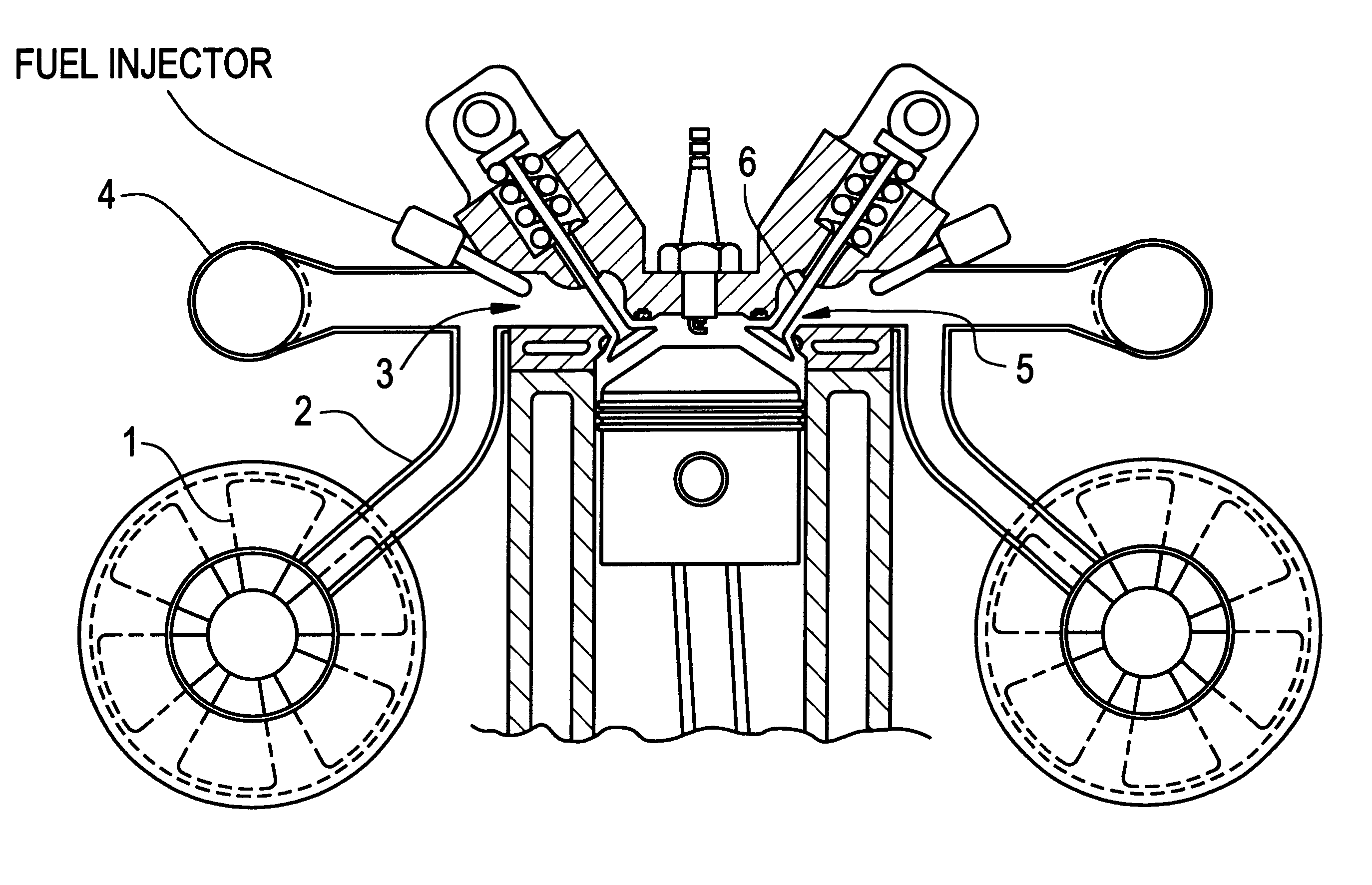
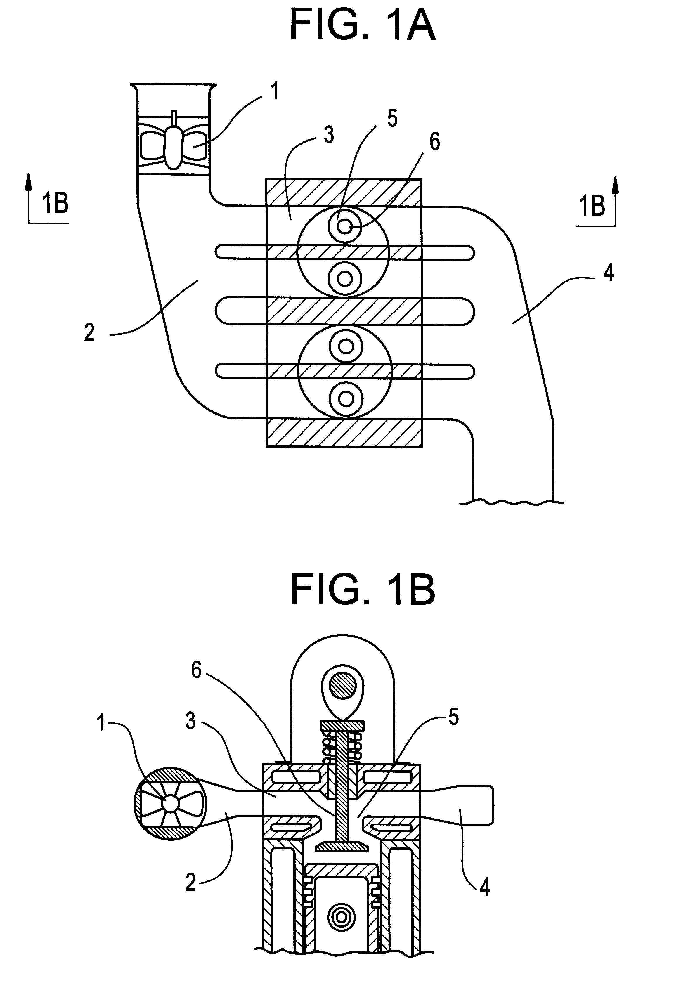
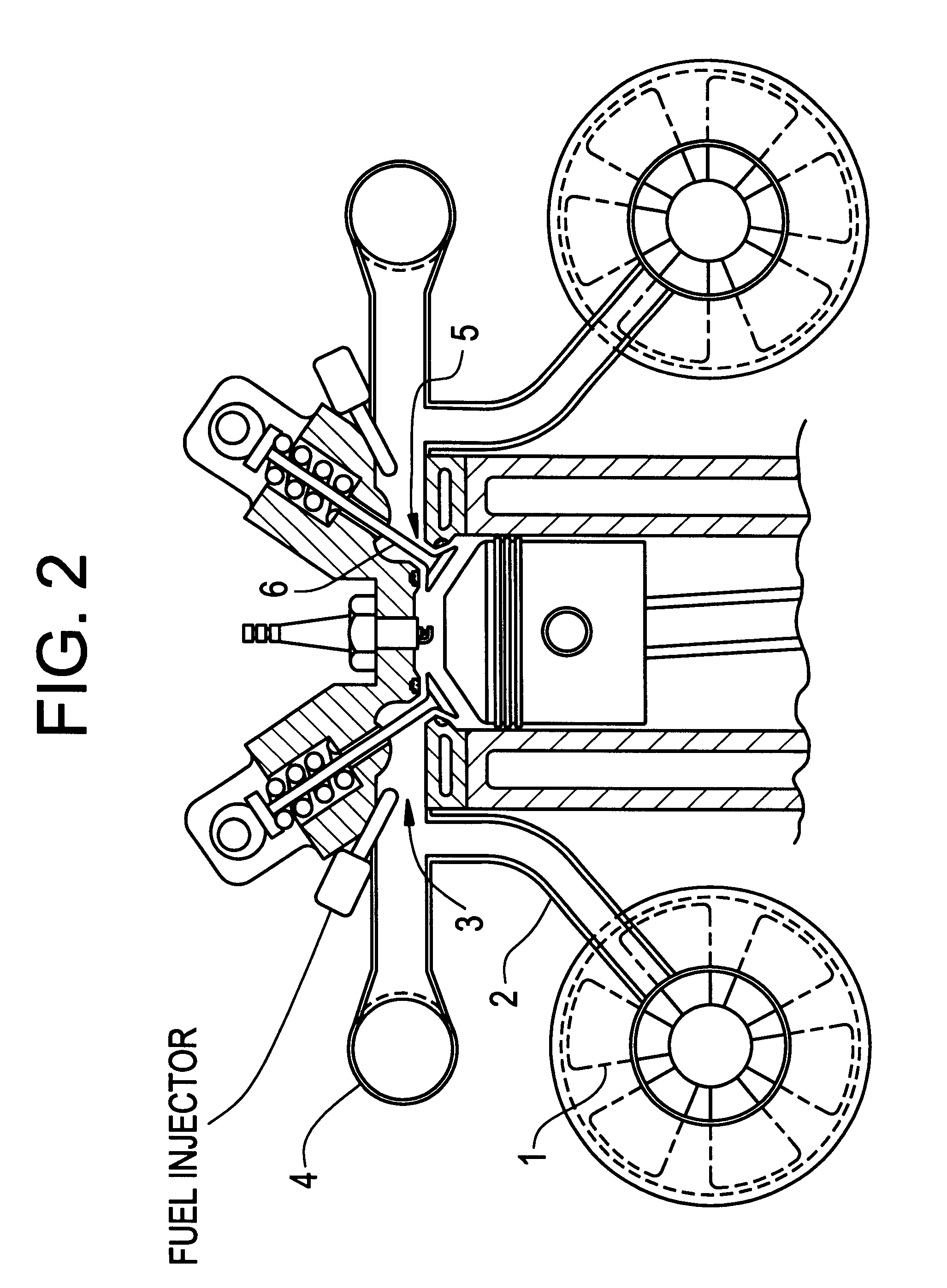
In the system of the invention all valves of the cylinder (both the intake and the exhaust valves of conventional engines) are driven simultaneously to accomplish the dual-duty, or dual-function, of exhausting combustion gases into passages external to the cylinder and then (in the next power cycle) admitting fresh air from the same passages into the cylinders. To said passages a continuous supply of air is forced to flow, by means of a fan (or a blower, or a compressor) driven by the engine, in order to sweep away combustion gases during the exhaust stroke and feed sufficient air during the intake stroke.

During the exhaust stroke the flow of air being supplied will be slowed down by the outcoming exhaust gases, while during the intake stroke the flow of air will be accelerated by the suction effect (or vacuum) produced by the piston moving away, while during the compression and power strokes the flow of air supplied will not be disturbed. Therefore, it may be estimated that the vol...


PUM


Abstract

Breathing system for four-stroke, fuel injected internal combustion engines, wherein each poppet valve of each cylinder accomplishes a dual-duty to serve both as an exhaust valve (in the final process of a given cycle) and subsequently as an inlet valve (in the first process of the following cycle). The passages (external to the cylinder) where the valve ports and stems are located are connected to both the intake and the exhaust manifolds wherein air is forced to flow under pressure by means of a fan (or a blower or a compressor) driven by the engine, in order to sweep away the combustion gases during the exhaust process and subsequently to feed a sufficient amount of fresh air during the intake process.

Description

BACKGROUND AND ADVANTAGES OF THE SYSTEM OF THE INVENTIONThe effective (or brake) horsepower (bhp) that an internal combustion engine can deliver is limited to a great extent by the fluid friction losses, or pressure losses, generated both during exhaust of combustion gases from the cylinder (through the exhaust valves) and intake of air to the cylinder (through the intake valves). Such pressure losses increase the mean effective pressure that the piston has to overcome both during the exhaust stroke and the intake stroke, resulting in work being wasted in each cycle and consequently in less useful effective power being delivered by the engine.Furthermore, the pressure losses during the intake process also reduce the unit air charge (weight or mass of air drawn into the cylinder per intake stroke) and therefore less fuel can be burned effectively in the combustion process. Consequently, this smaller unit air charge also reduces the thermal energy delivered by the combustion process i...

Claims


Application Information

Patent Timeline
IPC IPC(8): F02F1/42F02B33/40F02B33/00F02B75/02
CPCF02F1/4285F02B33/40F01N2270/08F02B2075/027
Inventor DE FRANCISCO, ROBERTO FORERO
Owner DE FRANCISCO ROBERTO FORERO
Why Eureka
Try Eureka