Piston engine cylinder head with combined functions

Active Publication Date: 2021-09-28
CANADAVFD CORP LTD
View PDF3 Cites 3 Cited by
  • Summary
  • Abstract
  • Description
  • Claims
  • Application Information

AI Technical Summary

Benefits of technology

This patent is about a new technology that allows for better control of engine performance by controlling the movement of the cylinder head. The technology also explains how changes in phase shift can impact the compression ratio of the engine. The main benefit of this technology is that it can improve engine performance without adding much cost or complexity.

Problems solved by technology

There are certain disadvantages relating to the existing prior art piston engines:1) In traditional four-stroke engine, multiple intake and exhaust valves are used, this makes the piston engine bigger in size and costly in manufacturing;2) In traditional four-stroke engine, the minimum combustion chamber volume is at the position of the top dead center (TDC) of the piston; the minimum combustion chamber volume position is the crank angle where the maximum combustion pressure can be achieved for a given amount of fuel.
When the peak pressure position (PPP) is near the top dead center (TDC), the torque produces on the crankshaft is low or even nearly zero, it is almost impossible to adjust the position of minimum combustion chamber in prior art engine;3) In two-stroke opposed piston engine, intake and exhaust valves are simplified as an exhaust port and an intake port, but this configuration causes excessive lubrication oil consumption, because cylinder lubrication oil is over exposed to intake air / gases when pistons moving from their top dead centers (TDCs) to their bottom dead centers (BDCs);4) In two-stroke opposed piston engine, the minimum combustion chamber volume is near the position(s) of the top dead center(s) (TDCs) of the piston(s), the minimum combustion chamber volume position is the crank angle where the maximum combustion pressure can be achieved for a given amount of fuel.
When the peak pressure position (PPP) is farther away from the position of minimum combustion chamber volume, the torque on the crankshaft is low, it is very complex to adjust the position of minimum combustion chamber volume position in two-stroke opposed engine.

Method used


Image

  • Piston engine cylinder head with combined functions
  • Piston engine cylinder head with combined functions
  • Piston engine cylinder head with combined functions

Examples


example 1

[0127]In example 1, there is provided a working sequence of embodiments of the present invention.

[0128]Referring to FIG. 6.

[0129]Wherein port A is used as exhaust port and port B is used as intake port, main piston 301 moves up and down in main cylinder 300. The movement (position) of piston 301 is the same as in prior art piston engines, it is shown as curve 603.

[0130]The movement of upper piston 302 is shown as curve 602.

[0131]The combustion chamber volume is shown as curve 604.

[0132]The x-axis is crank angle of the main piston.

[0133]There are four strokes in one complete working cycle.

[0134]Stroke 1, Compression.

[0135]Compression takes place from near 180° BTDC (or 540° ATDC) to near 45° ATDC, Firstly while main piston 301 moves from its BTD to its TDC, the upper piston 302 stays still vertically at its zero position, and secondly while main piston 301 further moves downwards to its BDC again, the upper piston 302 moves downwards from its position zero toward its TDC1 position.

[0...

example 2

[0163]In Example 2, there is provided another working sequence of embodiments of the present invention.

[0164]Refer to FIG. 7A. where port B is used as exhaust port and port A is used as intake port.

[0165]The combustion stroke and compression are the same as that in Example 1.

[0166]Exhaust stroke.

[0167]From near 180° ATDC to 360° ATDC, when main piston 301 moves from its BDC position towards its TDC position, upper piston 302 moves upwards to its uppermost position BDC1 and Port B is opened and port A is closed, air / gas contained in the combustion chamber exhausts to external.

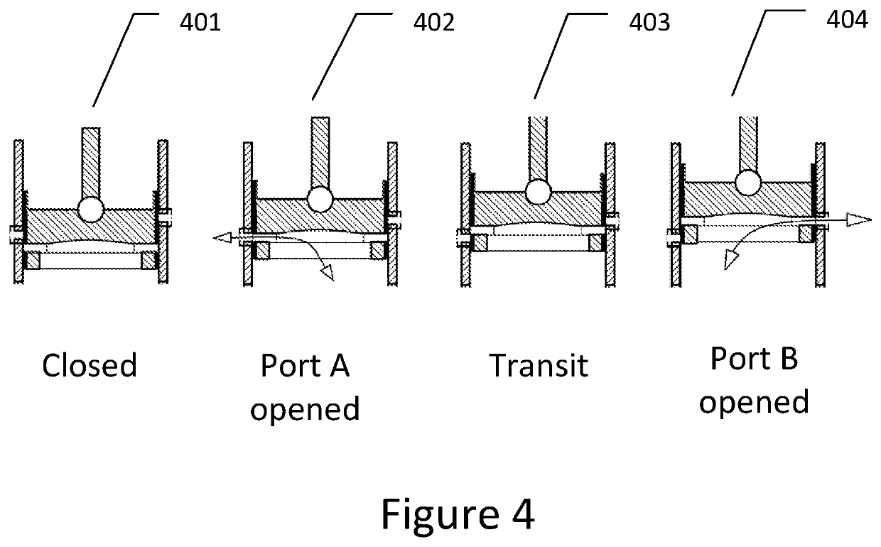
[0168]In exhaust stroke, port B is opened and port A is closed, and the combustion chamber is communicated with external, as 404 in FIG. 4

[0169]Intake Stroke.

[0170]From near 360° ATDC to near 540° ATDC, upper piston 302 moves downwards, port A is opened and port B is closed, air / gas enters into combustion chamber.

[0171]At the position near 360° ATDC, there is a transit where both Port A and port B are closed, as...

example 3

[0179]In Example 3, there is provided a third working sequence of embodiments of the present invention.

[0180]The compression ratio adjustment can be fulfilled by a phase-shifting in crank angle of upper piston working sequence.

[0181]Referring to working sequence 602 and 702 in FIG. 6 and FIG. 7FIG. 7A, where both working sequences are defined as neutral sequences because there are no phase shift in crank angle.

[0182]When the upper piston working sequences 602 and 702 are configured leading or lagging a certain crank angle to the neutral sequences, the correspondent minimum combustion chambers are increased or decreased, and so that the compression ratios are deceased or increased.

[0183]The details are shown in FIG. 7B.

[0184]Sequences 760 in FIG. 7B shows three phase shift examples.

[0185]Case one has a 0° leading in phase shift, which is the neutral sequence as is FIG. 6.

[0186]Case two has a 9° leading in phase shift with reference to the neutral sequence.

[0187]Case three has a 9° la...


PUM


Abstract

A movable piston head is provided; the piston head has a head cylinder and a upper piston, a first port and a second port on the head cylinder wall, a first path and a second path in the upper piston, when the first port aligns with the first path horizontally, or the second port aligns with the second path horizontally, the combustion chamber is communicating with external, the upper piston moves up and down to perform intake, exhaust, compression, seal the combustion chamber from external. A variable compression ratio engine and a shifted minimum combustion chamber volume engine are provided. Fuel efficiency is improved and manufacturing cost is reduced, different working sequences and compression ratio control are also provided in the invention.

Description

FIELD OF THE INVENTION[0001]The present disclosure relates to piston engine. More specifically, the present disclosure relates to a novel piston engine cylinder head which combines variable compression ratio adjustment, intake and exhaust controls. The fuel efficiency is improved and manufacturing cost is reduced.BACKGROUND OF THE INVENTION[0002]There are certain disadvantages relating to the existing prior art piston engines:[0003]1) In traditional four-stroke engine, multiple intake and exhaust valves are used, this makes the piston engine bigger in size and costly in manufacturing;[0004]2) In traditional four-stroke engine, the minimum combustion chamber volume is at the position of the top dead center (TDC) of the piston; the minimum combustion chamber volume position is the crank angle where the maximum combustion pressure can be achieved for a given amount of fuel. When the peak pressure position (PPP) is near the top dead center (TDC), the torque produces on the crankshaft is...

Claims


Application Information

Patent Timeline
IPC IPC(8): F02D15/04F02B75/04F02B75/02F02B3/06
CPCF02D15/04F02B75/044F02B3/06F02B75/042F02B2075/027F02B75/28F01B7/02Y02T10/12
Inventor YUAN, DEFANGZHAO, LIN
Owner CANADAVFD CORP LTD
Why Eureka
Try Eureka