Magnetic field generating device and offset calculating method
- Summary
- Abstract
- Description
- Claims
- Application Information
AI Technical Summary
Benefits of technology
Problems solved by technology
Method used
Image

Examples
example 1
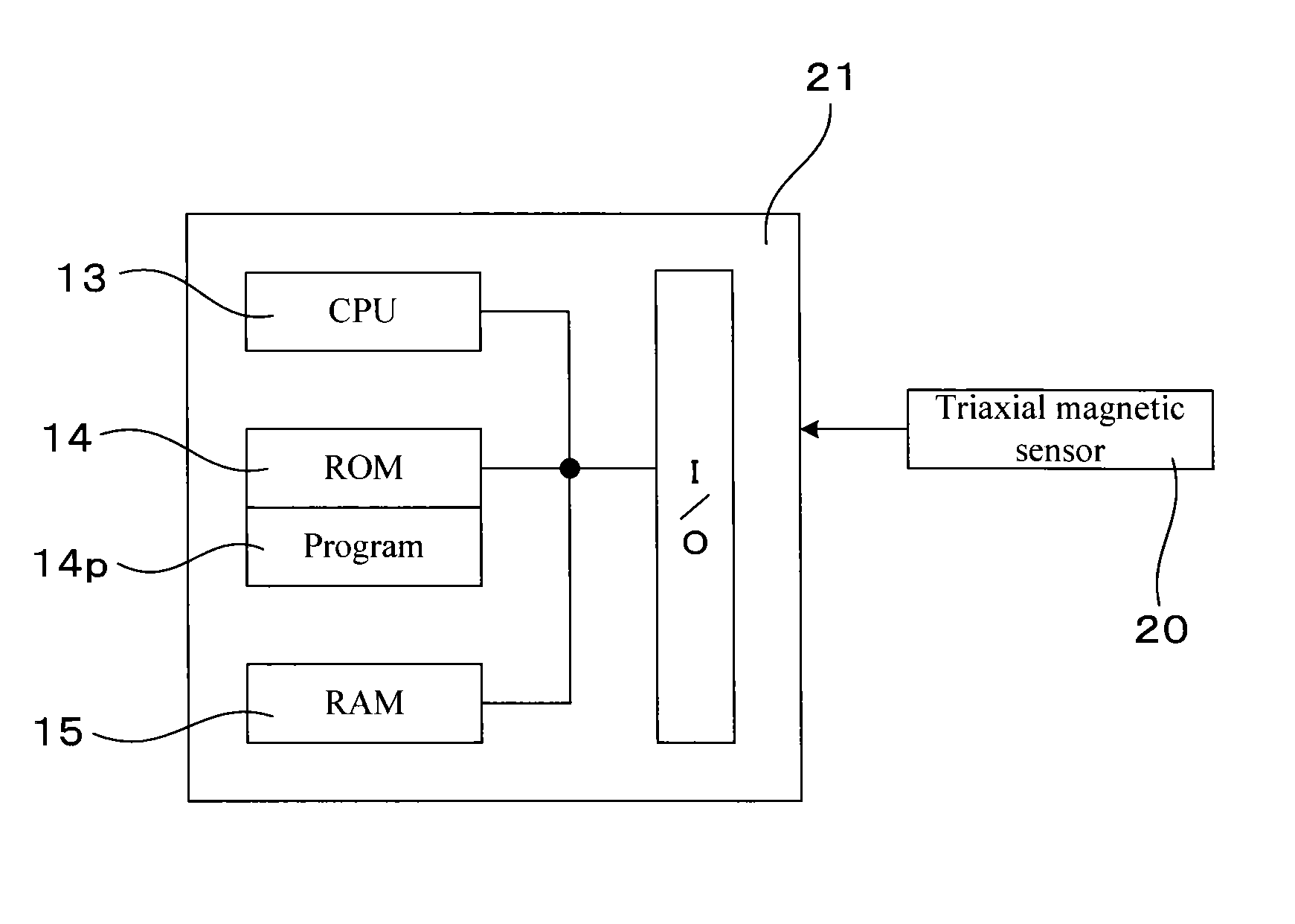
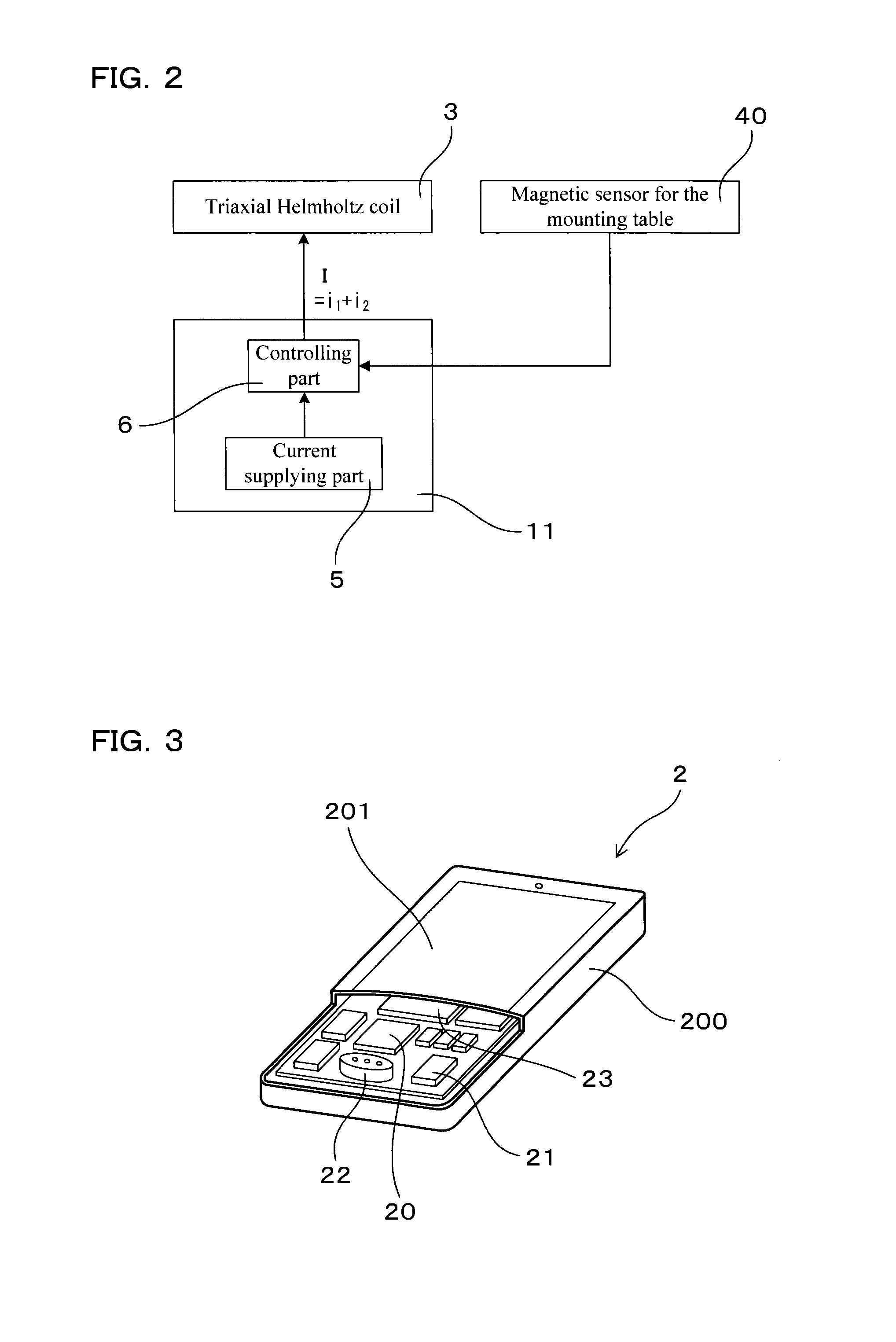
[0056]Examples relating to the magnetic field generating device and the offset calculating method will be explained by use of FIGS. 1 to 10. A magnetic field generating device 1 of this Example generates a magnetic field which acts on a portable device 2 (see FIGS. 1 and 3). As shown in FIG. 3, the portable device 2 has a triaxial magnetic sensor 20 and an offset calculating part 21. The triaxial magnetic sensor 20 detects geomagnetism as a magnetic vector OMe within a triaxial orthogonal coordinate system (XYZ: see FIG. 5) fixed in the portable device 2 when a user uses the portable device 2. The offset calculating part 21 calculates a center point O′ of an azimuth sphere 7 drawn within the triaxial orthogonal coordinate system by a detected value Me of geomagnetism along with a change in posture of the portable device 2 when used by the user.
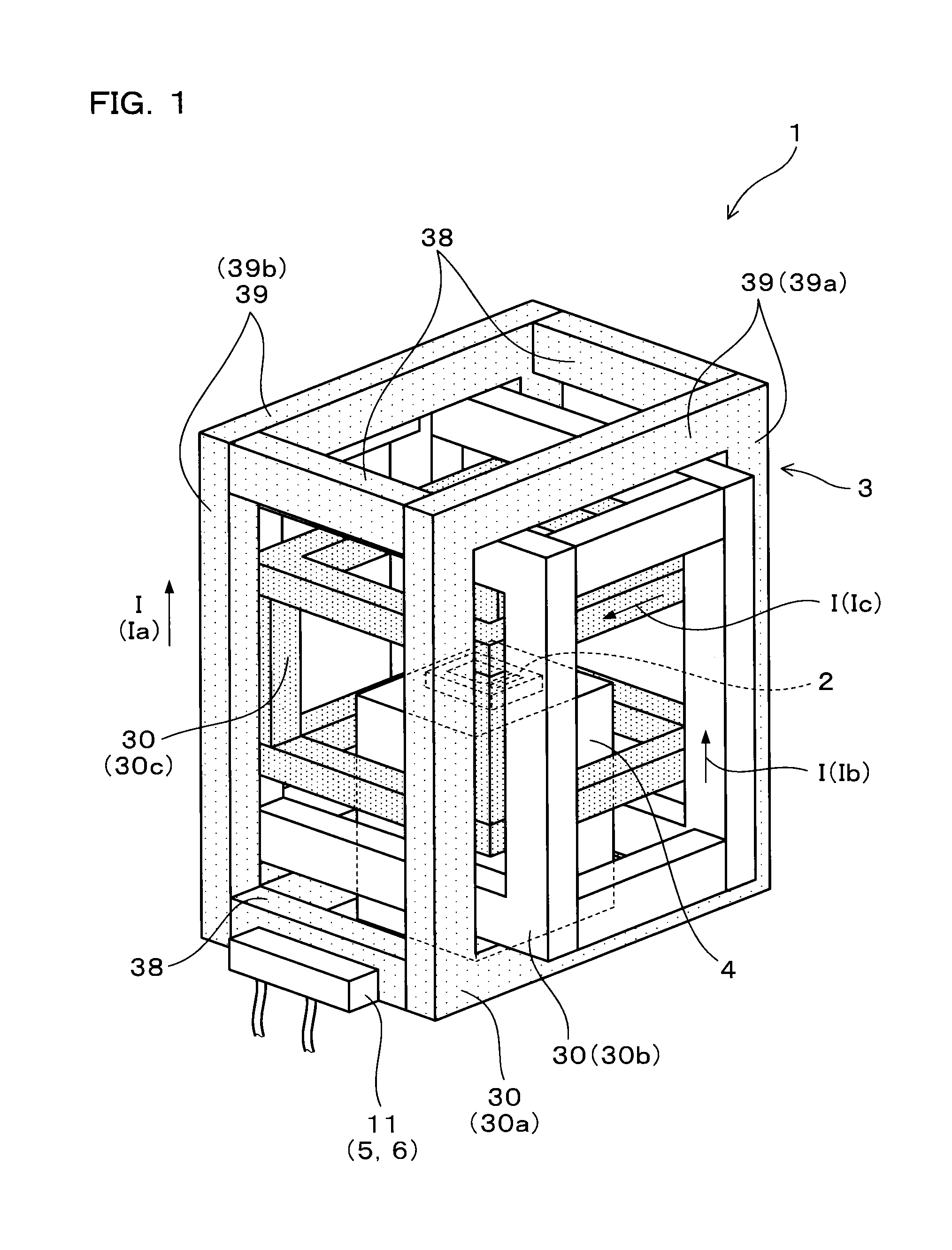
[0057]As shown in FIG. 1, the magnetic field generating device 1 of this Example includes a triaxial Helmholtz coil 3, a mounting table 4, a ...
example 2
[0085]This Example is an example wherein the number of detected values Ma of the synthetic magnetic field is changed. As shown in FIG. 11, in this Example, the direction of the synthetic magnetic field is changed so as to rotate by 360° around the X, Y and Z axes, respectively. One detected value Ma is acquired each time the direction of the synthetic magnetic field rotates by 45° so that eight detected values Ma for the respective one axis, namely, twenty four detected values Ma for the three axes, in total, are acquired. The thus-acquired detected values Ma are apart from each other on the azimuth sphere 7, and are evenly present on the azimuth sphere 7. Therefore, the coordinates of the center point O′ on the azimuth sphere 7 can be precisely calculated by using the detected values Ma.
[0086]The configuration as described above enables the synthetic magnetic field to act on the triaxial magnetic sensor 20 so as to include six directions (A, B, C, D, E, F) mutually different in ang...
example 3
[0088]This Example is an example wherein a method of using the magnetic field generating device 1 is changed. In this Example, after new development of the program 14p for offset calculation (see FIG. 4), the magnetic field generating device 1 is used when this program is evaluated.
[0089]As explained in Example 1, a user, when carrying out the calibrating operation, subjects the portable device 2 to the rotating operation such as the front-back reverse operation in a manner of drawing a figure of eight. This operation changes the direction of the portable device 2 to the geomagnetism. At this time, the detected value Me of the geomagnetism obtained by the triaxial magnetic sensor 20 changes as shown in FIG. 5, for example, and moves on the azimuth sphere 7 along with a change in posture of the portable device 2. The offset calculating part 21 acquires detected values Me of the geomagnetism at a plurality of points during the calibrating operation, and calculates the center point O′ ...
PUM
 Abstract
Description
Claims
Application Information
 - R&D
- Intellectual Property
- Life Sciences
- Materials
- Tech Scout
- Unparalleled Data Quality
- Higher Quality Content
- 60% Fewer Hallucinations
Browse by: Latest US Patents, China's latest patents, Technical Efficacy Thesaurus, Application Domain, Technology Topic, Popular Technical Reports.
© 2025 PatSnap. All rights reserved.Legal|Privacy policy|Modern Slavery Act Transparency Statement|Sitemap|About US| Contact US: help@patsnap.com