RFID transponder, in particular for assembly on metal and manufacturing method therefor

Active Publication Date: 2013-11-05
FRAUNHOFER GESELLSCHAFT ZUR FOERDERUNG DER ANGEWANDTEN FORSCHUNG EV
View PDF3 Cites 8 Cited by
  • Summary
  • Abstract
  • Description
  • Claims
  • Application Information

AI Technical Summary

Benefits of technology

[0005]It is thus the object of the present invention to provide a compact RFID transponder which is as completely planar as possible, which is technically

Problems solved by technology

In addition, such a design is rather complex and expensive; furthermore, a corresponding structure is also difficult to modify (for example, when another chip should be used

Method used


Image

  • RFID transponder, in particular for assembly on metal and manufacturing method therefor
  • RFID transponder, in particular for assembly on metal and manufacturing method therefor
  • RFID transponder, in particular for assembly on metal and manufacturing method therefor

Examples


first embodiment

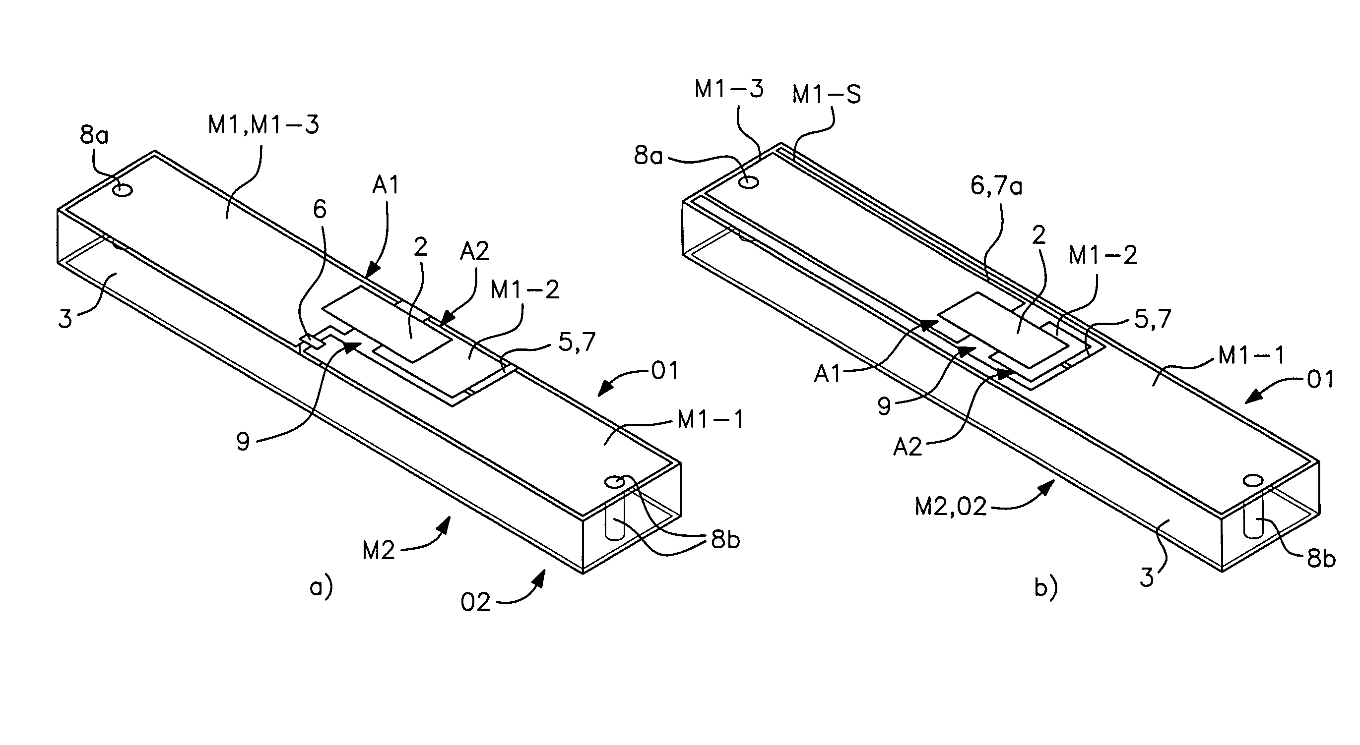
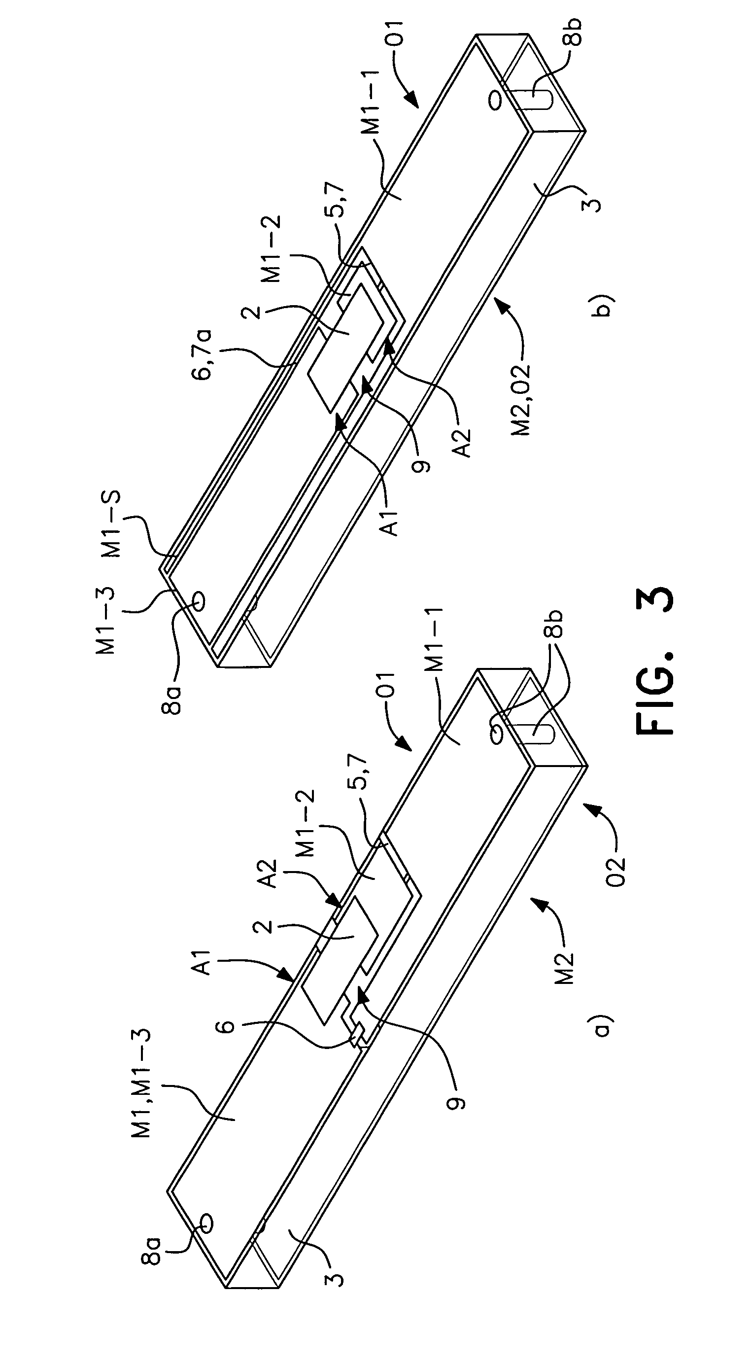
[0046]The first metallization layer M1 formed on the upper side O1 of the carrier element 3 is now structured in the RFID transponder in accordance with the invention shown (at the left) in FIG. 3a such that it forms the two electrical terminals A1 and A2 with which the chip 2 electrically contacts the antenna 1 and such that it forms the first capacitance Cser 5 connected in series with the chip 2. The metal layer M1 for this purpose has a thin, slot-shaped break 7. The metal layer M1 is thus completely removed from the upper side O1 of the carrier element 3 in the region of this electrical break. A section of this narrow, slot-shaped break 7 extends perpendicular to the longitudinal direction, that is in the width direction on the surface O1 and divides, seen from the through hole 8b toward the through hole 8a, the metallization M1 into a first metallization section M1-1 and a second central metallization section M1-2.

[0047]There is then present, seen in the same direction, a furt...

second embodiment

[0050]FIG. 3b shows a second embodiment for an RFID transponder in accordance with the invention which is generally equally realized like the embodiment shown in FIG. 3a. Only the differences will therefore be described in the following.

[0051]Whereas in the case shown in FIG. 3a, a distributed first capacitance 5 and a concentrated, second capacitance 6 are formed, in the case shown in FIG. 3b not only the first capacitance 5 is formed (by means of a slot-shaped trench section) in a distributed manner, but also the second capacitance 6. For this purpose, the first metallization M1 has a further slot-shaped trench section, which is provided with the reference numeral 7a here, which extends in the longitudinal direction of the carrier element 3 and which is connected to the transversely extending trench section 7 (which forms the first capacitance 5). This trench section 7a extends, seen in the longitudinal section, from the side of the chip facing the second through hole 8b over the ...


PUM

PropertyMeasurementUnit
Lengthaaaaaaaaaa
Lengthaaaaaaaaaa
Lengthaaaaaaaaaa

Abstract

An RFID transponder including an antenna, a chip having at least one transmission and reception circuit as well as a memory, a dielectric carrier element which is covered on a first surface with a structured first metallization and which is covered on a second surface disposed opposite the first surface with a second metallization. The first and second metallizations are mutually electrically conductively connected, thereby forming the antenna. The first metallization is structured such that it forms two electric terminals of the antenna arranged on the first surface of the dielectric carrier element. The chip can be or is electrically contacted via these two terminals. An adaptation network is at least partly formed by the structuring of the first metallization and adapting the input impedance of the antenna in a conjugate complex manner to the impedance of the chip.

Description

[0001]This application has a priority of European no. 09 007 225.7 filed May 29, 2009, hereby incorporated by reference.FIELD OF THE INVENTION[0002]The present invention relates to an RFID transponder and to a corresponding manufacturing method for an RFID transponder. The RFID transponder in accordance with the invention is in this respect in particular made so that it can be used in one of the UHF (ultra high frequency) bands 865-868 MHz (Europe), 902-928 MHz (Canada and the US) and 950-956 MHz (Japan).BACKGROUND OF THE INVENTION[0003]Currently, RFID systems are used very intensively and profitably in many areas, above all also in the logistics field. Very compact, flat RFID transponders (so-called tags) are required in many cases in this respect.[0004]Most known concepts for such RFID transponder antennas (that is tag antennas) such as so-called PIFA antennas (printed inverted F antennas) are in this respect not completely planar. They are produced on a conductive adhesive film a...

Claims


Application Information

Patent Timeline
IPC IPC(8): H01Q1/38H01Q7/00
CPCG06K19/07749H01Q1/2208H01Q1/2225H01Q1/38H01Q7/00Y10T29/49002
Inventor POPUGAEV, ALEXANDERWANSCH, RALNERBERNHARD, JOSEFPFLAUM, ALEXANDER
Owner FRAUNHOFER GESELLSCHAFT ZUR FOERDERUNG DER ANGEWANDTEN FORSCHUNG EV
Why Eureka
Try Eureka