Gripper, a conveying installation and a method for the operation of such a conveying installation

a conveying installation and gripper technology, applied in the field of conveying technology, can solve the problems of not being able to convey spatially extended objects with a different shape, requiring relatively much space in the receiving region of the conveying device, and being difficult to manufacture and maintain, so as to increase the number of gripper jaw pairs, the effect of increasing the efficiency and the conveying performance of the conveying installation

Inactive Publication Date: 2015-06-04
FERAG AG
View PDF1 Cites 2 Cited by
  • Summary
  • Abstract
  • Description
  • Claims
  • Application Information

AI Technical Summary

Benefits of technology

[0186]Such a conveying installation with respect to the third aspect provides the advantage that objects of different sorts can be transported in a groupwise manner without an arrangement and size of the groups being limited and / or determined by an arrangement and size of the members of the drive body.
[0187]For example, the efficiency and the conveying performance of the conveying installation can be increased by way of an increase in the number of gripper jaw pairs per gripper, without a limitation and / or predefining of the type of the conveyed objects and in particular of the size and / or arrangement of the groups of conveyed objects of the same sort being effected by way of this increase.

Problems solved by technology

Conveying devices with such grippers therefore require relatively much space in the receiving region.
This design, due to the shaping of the bow with two projecting tongues and an elongate pressing element is adapted to flat objects and is not suitable for conveying spatially extended objects with a different shape.
The actuation mechanism consists of several parts and is therefore complicated to manufacture and maintain.

Method used


Image

  • Gripper, a conveying installation and a method for the operation of such a conveying installation
  • Gripper, a conveying installation and a method for the operation of such a conveying installation
  • Gripper, a conveying installation and a method for the operation of such a conveying installation

Examples


Embodiment Construction

[0225]FIGS. 1 to 8 and 12 to 13 for the purpose of a better illustration of the invention show embodiments according to a not yet published patent application of the same applicant.

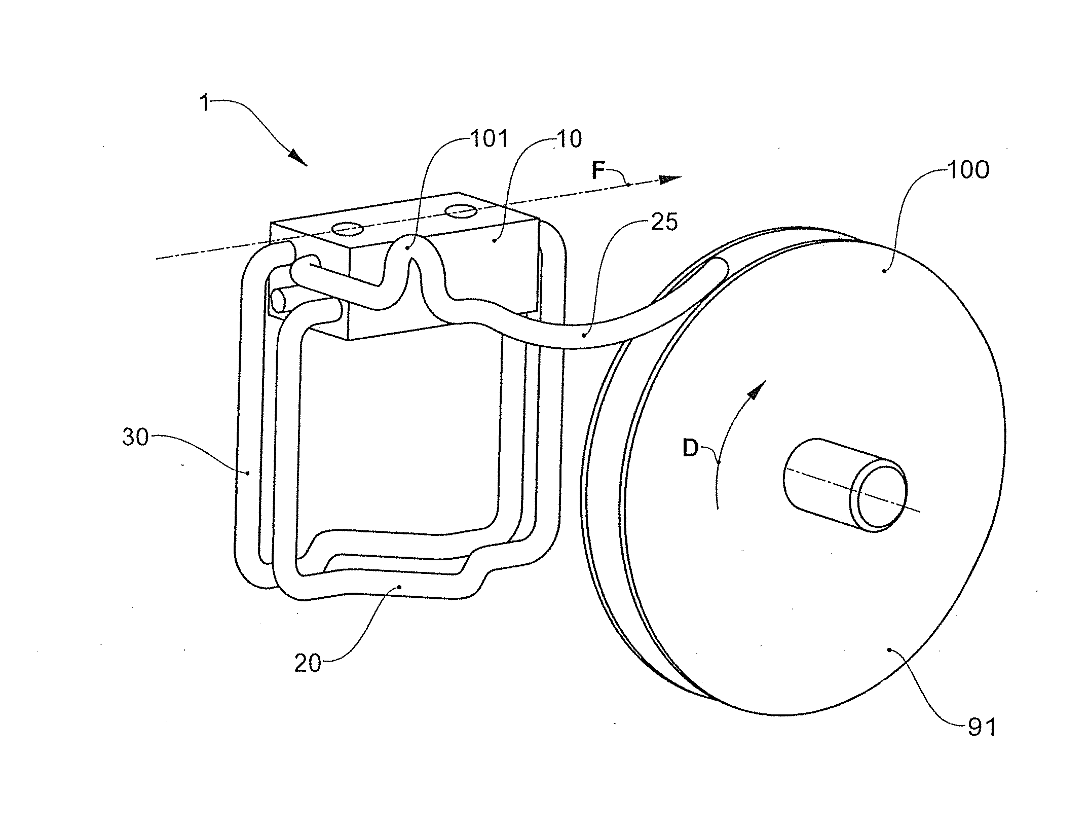
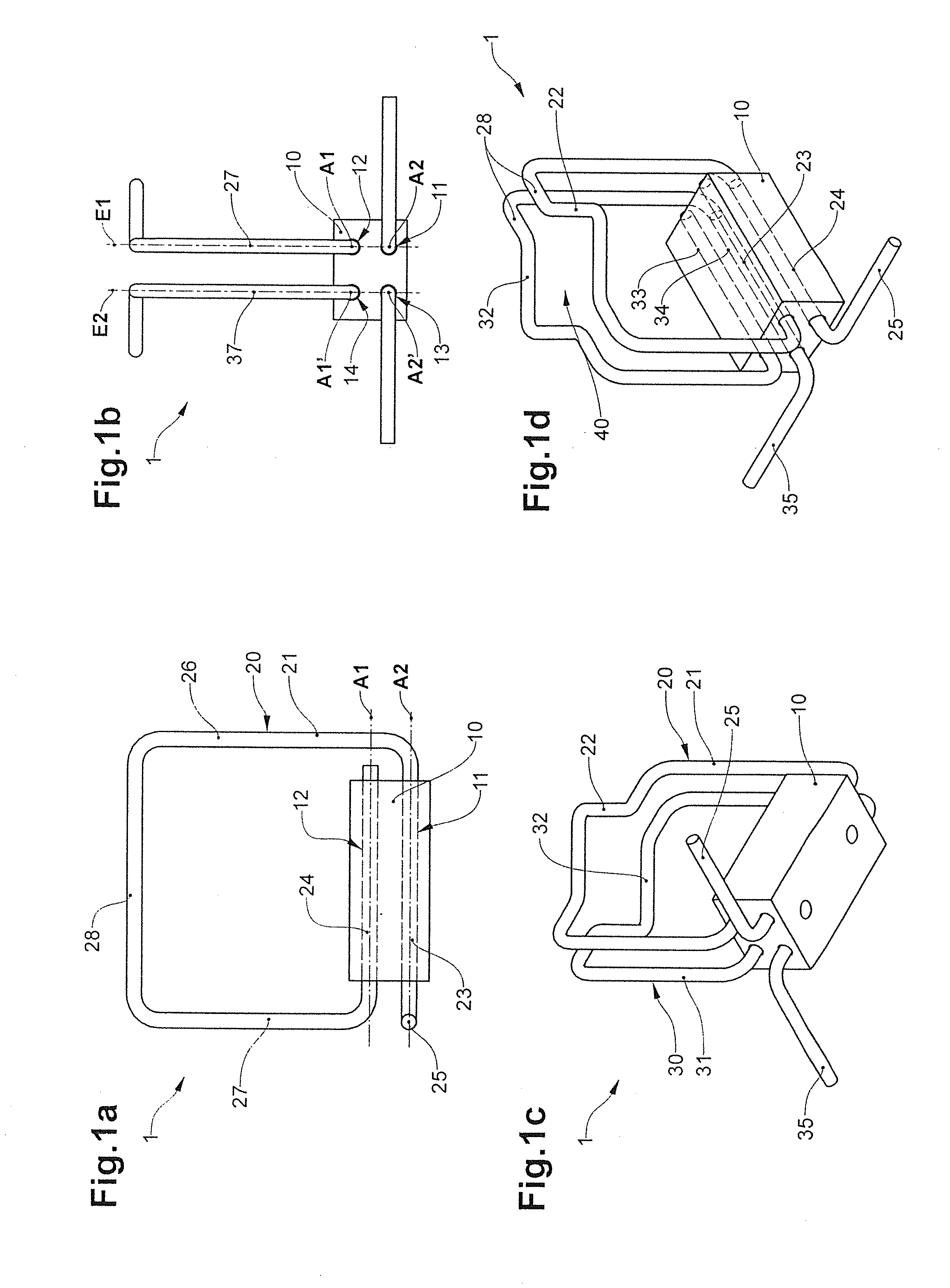
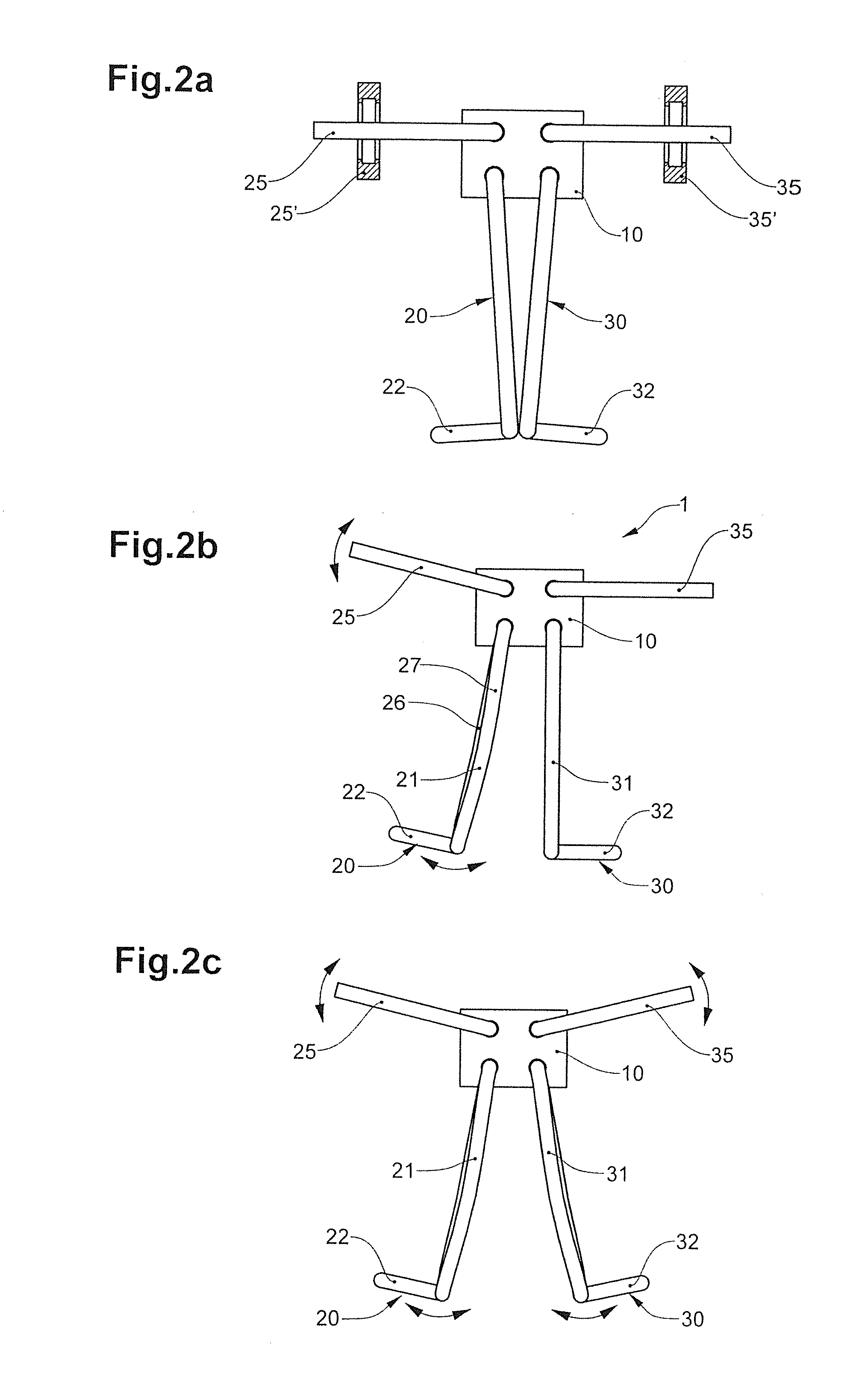
[0226]FIG. 1a-d shows a gripper 1 with a gripper body 10 and two gripper jaws 20, 30 in the form of bows 21, 31, in different views in the closed condition.

[0227]The gripper body 10 is essentially cuboid and comprises four tube-like recesses 11, 12, 13, 14 which are continuous in the longitudinal direction. As is shown in FIG. 3e, it can consist of several parts which are connected to one another, wherein the recesses are formed by grooves along the connection surfaces of these parts. Two of the recesses 11, 12 and 13, 14 in each case lie in a common plane E1 and E2 respectively and run parallel to one another. The gripper body 10 here includes additional elements that are not shown here and with which it can be coupled onto a drive body of a conveying installation.

[0228]The gripper jaws 20, 30 have the s...


PUM

PropertyMeasurementUnit
diameteraaaaaaaaaa
diameteraaaaaaaaaa
diameteraaaaaaaaaa

Abstract

A gripper for gripping and held conveying of objects as well as a corresponding conveying installation. The gripper has a first gripper jaw and a second gripper jaw. The gripper jaws can assume an open and a closed condition relative to one another, can exert a clamping force onto the object to be gripped, and a restoring force in the direction of the closed condition acts upon the gripper jaws. Moreover, at least one control element is present, which is capable of interacting with a switch. The control element is designed as a cam guide and has a functional contour with at least one arcuate contour segment. The conveying installation with opening locations that include a switch of a first and second type and control elements that either interact with the switch of the first type or the switch of the second type.

Description

BACKGROUND OF THE INVENTION[0001]1. Field of the Invention[0002]The invention lies in the field of conveying technology, and generally relates to a gripper for gripping and for the held conveying of objects, wherein the gripper includes a control element for actuating the gripper. The invention, moreover, relates to a conveying installation with a plurality of grippers with control elements for actuating the grippers.[0003]2. Description of Related Art[0004]Different examples of a gripper particularly suitable for gripping and conveying spatially extended, symmetrical objects, objects with a holding ring, hollow objects, and objects with different shapes and / or sizes are described in the following sections for a better illustration of the invention. The gripper in particular is suitable for gripping and conveying preforms for the production of receptacles of plastic, e.g. PET bottles.[0005]Such grippers, for example, are applied, in order to convey preforms for blow moulding of cont...

Claims


Application Information

Patent Timeline
Patent Type & Authority Applications(United States)
IPC IPC(8): B65G17/32
CPCB65G17/326B65G17/323B65G47/842B65G47/905B29C49/42069B65G47/90B65G2201/0235B29C49/4205B29C49/42073
Inventor MADER, CARL CONRAD
Owner FERAG AG
Why Eureka
Try Eureka