Relating to propylene oxide purification

Active Publication Date: 2015-06-11
SHELL USA INC
1 Cites 8 Cited by

AI-Extracted Technical Summary

Problems solved by technology

Direct oxidation of propylene with air or oxygen to form PO tends to provide low yields.
However, epoxidation processes also tend to form by-products and impurities that are more difficult to separate.
Also produced, however, are small amounts of other oxygen-containing compounds such as methanol, acetone, acetaldehyde, propionaldehyde and the like, as well as hydrocarbons, which are difficult to separate and often remain as impurities in the PO product even following conventio...

Benefits of technology

[0019]Purification of PO by distillation, and PO production as a whole, are very energy-intensive, particularly given the substantial size of the columns tha...

Abstract

A method of separating impurities from impure PO, the method comprising distilling impure PO in a distillation zone to provide distillate PO of enhanced purity, wherein heat is provided to the distillation zone by a bottoms reboiler and by an intermediate reboiler, the intermediate reboiler providing heat at a lower temperature than the bottoms reboiler. A suitable distillation system is also disclosed.

Application Domain

Technology Topic

Image

  • Relating to propylene oxide purification
  • Relating to propylene oxide purification

Examples

  • Experimental program(1)

Example

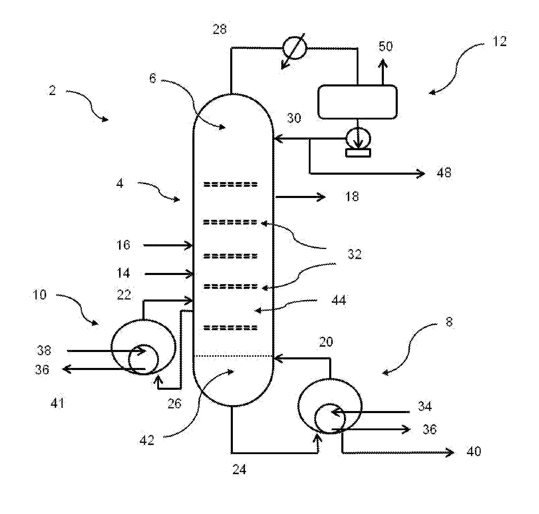
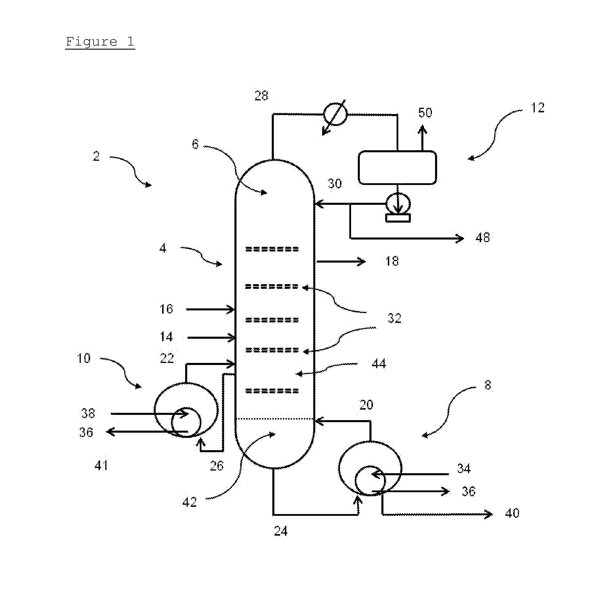
[0083]In order that the invention may be more readily understood, reference will now be made, by way of example, to the accompanying FIG. 1 showing a schematic view of a distillation column in accordance with one embodiment of the invention.
[0084]With reference to FIG. 1, a distillation system 2 for separating impurities from impure PO comprises a column structure 4 of walls and internals defining a distillation zone 6, a bottoms reboiler 8, an intermediate reboiler 10, and a reflux system 12.
[0085]The structure 4 of the system 2 defines an impure PO inlet 14 and an extractive distillation solvent inlet 16 into the distillation zone 6, and a purified PO outlet 18 from the distillation zone 6. Also defined are inlets 20, 22 and outlets 24, 26 for the bottoms reboiler 8 and the intermediate reboiler 10, as well as an overhead outlet 28 and a reflux inlet 30. From bottom to top of the column 2, the outlet 24 to the bottoms reboiler 8 is lowermost, followed by the inlet 20 from the bottoms reboiler 8, the outlet and inlet 26, 22 to and from the intermediate reboiler 10 which are at the same level, the impure PO inlet 14, the extractive solvent inlet 16, the purified PO outlet 18, the reflux inlet 30, and the overhead outlet 28.
[0086]Column trays 32 are provided between the inlets and outlets to aid distillation in the distillation zone 6. In particular, the column structure 2 comprises eleven theoretical trays between the inlet 20 from the bottoms reboiler and the outlet and inlet 26, 22 of the intermediate reboiler, nine theoretical trays between the outlet and inlet 26, 22 of the intermediate reboiler and the impure PO inlet 14, forty-five theoretical trays between the impure PO inlet 14 and the extractive distillation solvent inlet 16, six theoretical trays between the extractive distillation solvent inlet and the purified PO outlet 18 and six theoretical trays between the purified PO outlet and the overhead outlet 28 and reflux inlet 30. The theoretical trays are implemented in practice using conventional column trays but can also be executed as random or structured packing in other embodiments.
[0087]The bottoms reboiler 8 is a thermosyphon reboiler powered by an input of relatively high temperature steam 34, e.g. HP or MP steam, with condensate 36 being withdrawn. To provide an impurity outlet for the distillation zone 6, the bottoms reboiler 8 comprises a bleed 40 for bleeding off liquid components, in particular extractive distillation solvent enriched in impurities.
[0088]The intermediate reboiler 10 is a thermosyphon reboiler powered by an input of lower temperature steam 38, e.g. LP steam, with condensate 36 being withdrawn.
[0089]In operation, impure PO and ethyl benzene as extractive distillation solvents are supplied to the distillation zone via their inlets. The impure PO comprises approximately 99.6% wt PO, about 3500 ppm wt propionaldehyde, about 250 pm wt propylene derivatives having from 4 to 7 carbon atoms per molecule, and a balance of other impurities.
[0090]The bottoms reboiler 8 inputs heat into a bottoms region 42 of the distillation zone 6. The intermediate reboiler 10 inputs heat into a remaining, upper region 44 of the distillation zone 6. The intermediate reboiler represents about 70% of the overall reboiler duty. The remainder of the reboiler duty is assumed by the bottoms reboiler 8.
[0091]The provided heat results in distillation within the distillation zone. Distillate PO 18 of improved purity, with the concentration of impurities reduced by more than 95%, is withdrawn from the distillation zone, as is a bottoms bleed 40 of ethyl benzene enriched in impurities. The reflux system 12 of the reboiler, which includes a liquid impurity outlet 48 and vent 50, is controlled accordingly.
[0092]The column 2 is operated such that that all the consecutive trays between the inlet 22 from the intermediate reboiler and the purified PO outlet 18 conform to a flat temperature profile, i.e. have tray temperatures lying within 20° C. In particular, the temperature of these trays is maintained in the range of from 50° C. to 70° C. for the specific operating pressure considered. The intermediate reboiler 10 is thus able to operate on LP steam 38 having a temperature of about 130° C. and a pressure of about 2.5 bar abs. Such low grade steam 38 may result from one or more energy saving measures elsewhere.
[0093]By contrast, the maximum temperature of the bottoms region 42 is about 170° C. To provide this temperature, the bottoms reboiler is operated on MP steam 34 having a temperature of about 220° C. and a pressure of about 18 bar abs.
[0094]The ability to use LP steam 34 in the intermediate reboiler 10 lowers the overall demand for HP steam for the bottoms reboiler 8. Furthermore, with the number of theoretical trays between the input of the bottoms reboiler 8 and the input of the intermediate reboiler 10 being low, the detrimental effect of the intermediate reboiler 10 supplying some heat further up the column 2 is minimised.
[0095]It will be appreciated by those skilled in the art that a great number of modifications could be made to the column 2 without departing from the invention. For example the feeds, trays and column design as a whole could be varied whilst still accommodating the bottoms and intermediate reboilers. In one embodiment, the column is modified to be a conventional distillation column operating without extractive distillation solvent to accommodate an impure PO feed calling for such a setup.
[0096]In another embodiment an existing column, having a bottoms reboiler only, is extended with an additional bottoms stripper with bottom reboiler, which takes the function of the original bottoms reboiler by taking the original bottoms flow as feed and returning its overhead vapour in the original column. The distillation zone of the column is thus extended downwards. The original bottoms reboiler is converted to use low level heat and acts as an intermediate reboiler in the new configuration.

PUM

no PUM

Description & Claims & Application Information

We can also present the details of the Description, Claims and Application information to help users get a comprehensive understanding of the technical details of the patent, such as background art, summary of invention, brief description of drawings, description of embodiments, and other original content. On the other hand, users can also determine the specific scope of protection of the technology through the list of claims; as well as understand the changes in the life cycle of the technology with the presentation of the patent timeline. Login to view more.

Similar technology patents

Character Display Module

ActiveUS20100213836A1Space and cost savingEnergy saveDischarge tube screensAnimal watering devicesCost savingsPrinted circuit board
Owner:WINSTAR DISPLAY

Classification and recommendation of technical efficacy words

Why Eureka
Try Eureka