Vehicle seat

a seat and vehicle technology, applied in the field of seats, can solve problems such as objectionable touch of the seat part, and achieve the effect of improving the design value of the sea

Active Publication Date: 2015-06-18
TACHI S CO LTD
View PDF17 Cites 11 Cited by
  • Summary
  • Abstract
  • Description
  • Claims
  • Application Information

AI Technical Summary

Benefits of technology

[0029]Therefore, the vehicle seat of the present invention not only makes it possible for a seat occupant to enjoy a comfortable seating thereon, without feeling any objectionable touch, but also prevents the functional element from being deformed by the seat occupant sitting on the seat, while permitting the functional element to fully perform its utilitarian function. without being disturbed by the seat occupant. In addition, a design value of the vehicle seat can be improved.

Problems solved by technology

However, the functional element of such hard material directly contacts the seat occupant sitting on the seat, which gives the seat part an objectionable touch.

Method used


Image

  • Vehicle seat
  • Vehicle seat
  • Vehicle seat

Examples


first embodiment

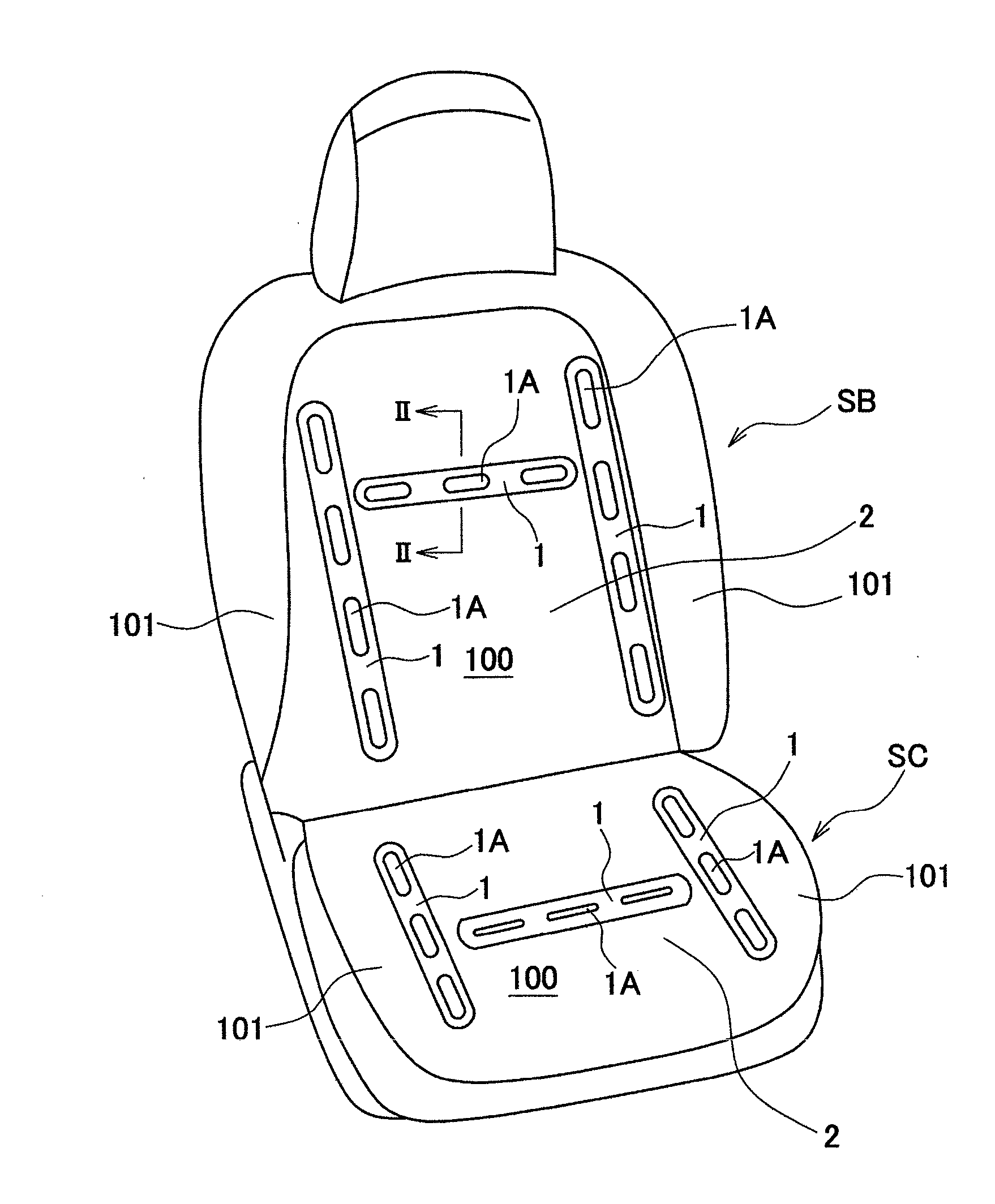
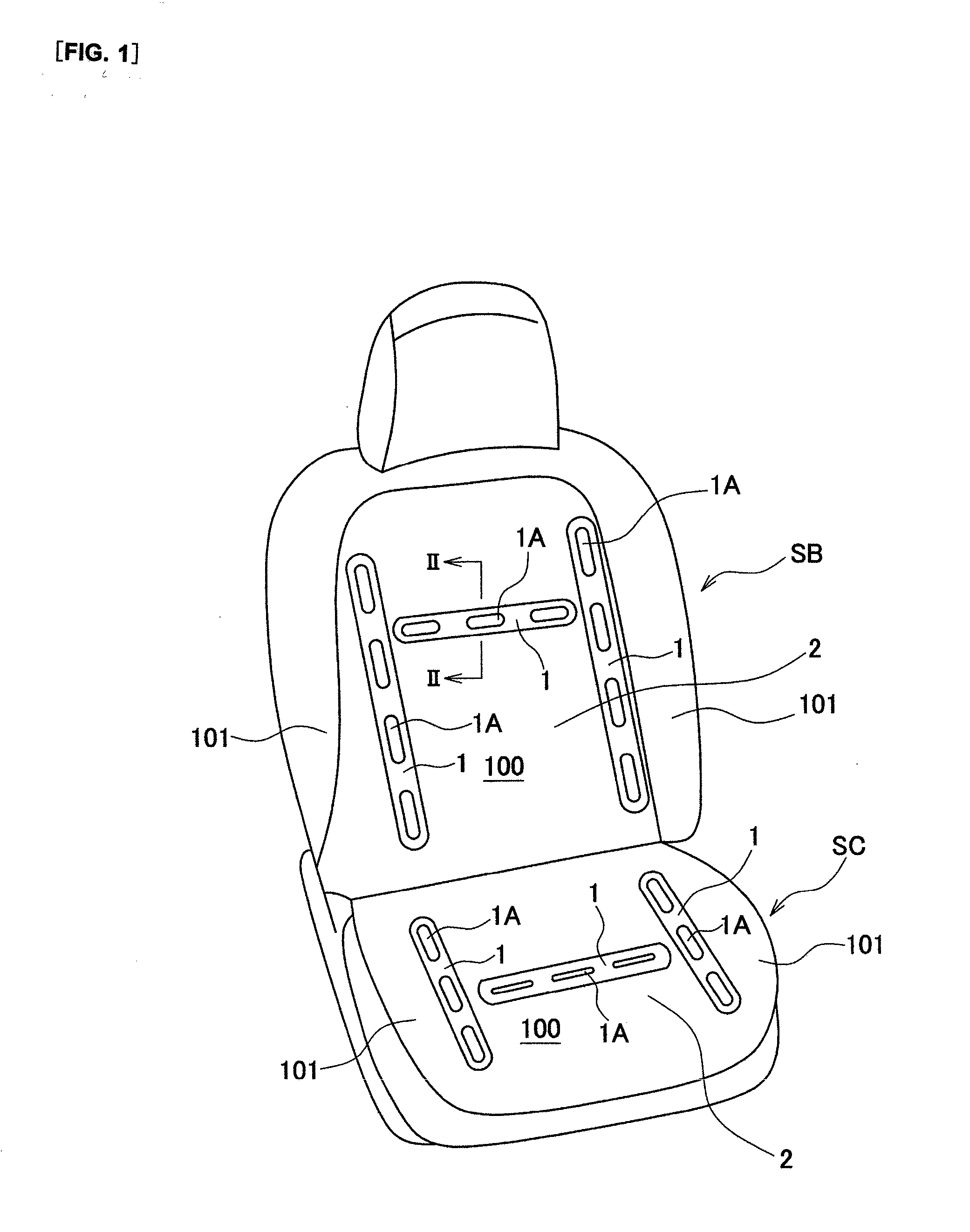
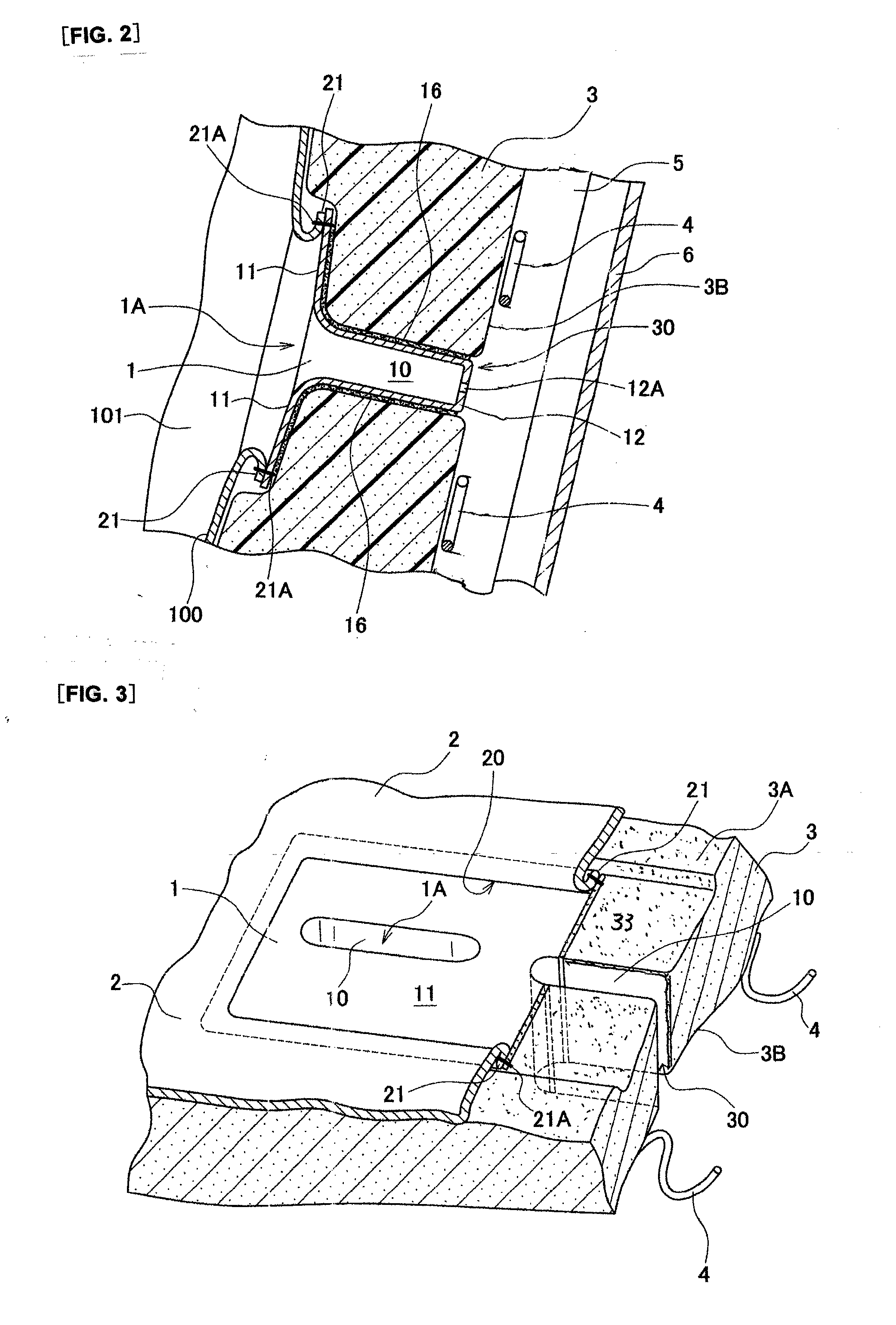
[0048]FIGS. 2 to 4 show the present invention. A functional element 1 shown in those Figures is adapted for use with a ventilated seat or the like, and is provided in the aforesaid support surface portions of the seat back SB and seat cushion SC. In the present embodiment, the functional elements 1 are each provided with air blowing holes as a utility function for air ventilation. In particular, the functional element 1 for the seat back constitutes air blowing holes through which air may be discharged outwardly from the inside of the seat back, whereas the functional element 1 for the seat cushion constitutes air blowing holes through which air may be discharged outwardly from the inside of the seat cushion. As shown in FIGS. 2 and 3, each of the functional elements comprises: a tubular body 10; and a flange 11 integral with the tubular body 10.

[0049]The tubular body 10 of the functional element is inserted and secured in a through-bore 30 formed in a foam padding 3 covered with a ...

second embodiment

[0057]FIG. 5 shows a second exemplary embodiment, which differs from the above-described first exemplary embodiment for securing the functional element to the padding. In the present second embodiment, an anchor place 13 is formed in the tubular body 10 of the functional element 1, instead of the adhesive 16 used in the preceding first mode. In particular, the functional element 1 is secured to the padding 3 by attaching the anchor piece 13 to the inner surface 3B of the padding 3. Thus, securing the functional element 1 to the padding 13 can be easily done by forcibly inserting the anchor piece through the through-bore of the padding, which expedites the securing process more efficiently than in the adhesive securing process using the adhesive 16.

[0058]FIG. 6 shows a third exemplary embodiment wherein the functional element is secured to the padding. In the present embodiment, it is to be understood that a plurality of securing through-holes are formed in the padding 3 so as to sur...


PUM


Abstract

A vehicle seat comprising a foam padding having a through-bore, a surface cover element covering a surface of the foam padding, and a functional element formed from a soft material. The functional element has a tubular body fitted in the through-bore of the foam padding and a flange integral with the tubular body. An area of the flange of the functional element, adjacent to a peripheral end of the flange, is sewn with a reverse side of an edge portion of an opening defined in the surface cover element, such reverse side facing to the foam padding. The surface cover element with the flange thus sewn therewith covers the foam padding, with the tubular body being fitted in the through-bore of the foam padding, so that a surface of the flange and an opening of the tubular body are exposed in an outer surface of the vehicle seat.

Description

CROSS REFERENCE TO RELATED APPLICATIONS[0001]The present application is a 35 U.S.C. §371 National Phase conversion of PCT / JP2013 / 067721, filed Jun. 27, 2013, which claims benefit of Japanese Application No. 2012-146380, filed Jun. 29, 2012, the disclosure of which is incorporated herein by reference. The PCT International Application was published in the Japanese language.TECHNICAL FIELD[0002]The present invention relates to a seat for use with a vehicle, such as an automobile seat. In particular, the invention is directed to a seat, which has a functional element provided in a surface of the seat in such a manner that the functional element is partly exposed therein, wherein the functional element includes a ventilation element, a cup holder, and a container for containing small articles therein, for example.BACKGROUND ART[0003]Conventionally, among the seats of the abovementioned kind, as disclosed for example from the undermentioned patent-related document 1, there is known a sea...

Claims


Application Information

Patent Timeline
Patent Type & Authority Applications(United States)
IPC IPC(8): B60N2/56B60N3/10B60N2/58B60N2/64
CPCB60N2/5621B60N2/5883B60N3/10B60N2/64A47C7/742A47C31/023B60N2/646B60N2/5664B60N2/5825B60N2/5875A47C31/02A47C7/74B60N2/58B60N2/5657
Inventor TAGUCHI, MASAYUKI
Owner TACHI S CO LTD
Why Eureka
Try Eureka