Drywall joist hanger

a joist hanger and drywall technology, applied in the direction of building components, building reinforcements, constructions, etc., can solve the problems of drywall use and generally inability to shield supporting structural members

Active Publication Date: 2015-06-18
SIMPSON STRONG TIE
View PDF41 Cites 39 Cited by
  • Summary
  • Abstract
  • Description
  • Claims
  • Application Information

AI Technical Summary

Benefits of technology

[0011]The present invention provides a connection that allows a joist hanger to be attached to a supporting structural member with...

Problems solved by technology

Such forces are often caused by lateral loading on the building due to high winds or seismic activity.
Drywall is used in fire barriers, but generally cannot be used to shield su...

Method used


Image

  • Drywall joist hanger
  • Drywall joist hanger
  • Drywall joist hanger

Examples


Embodiment Construction

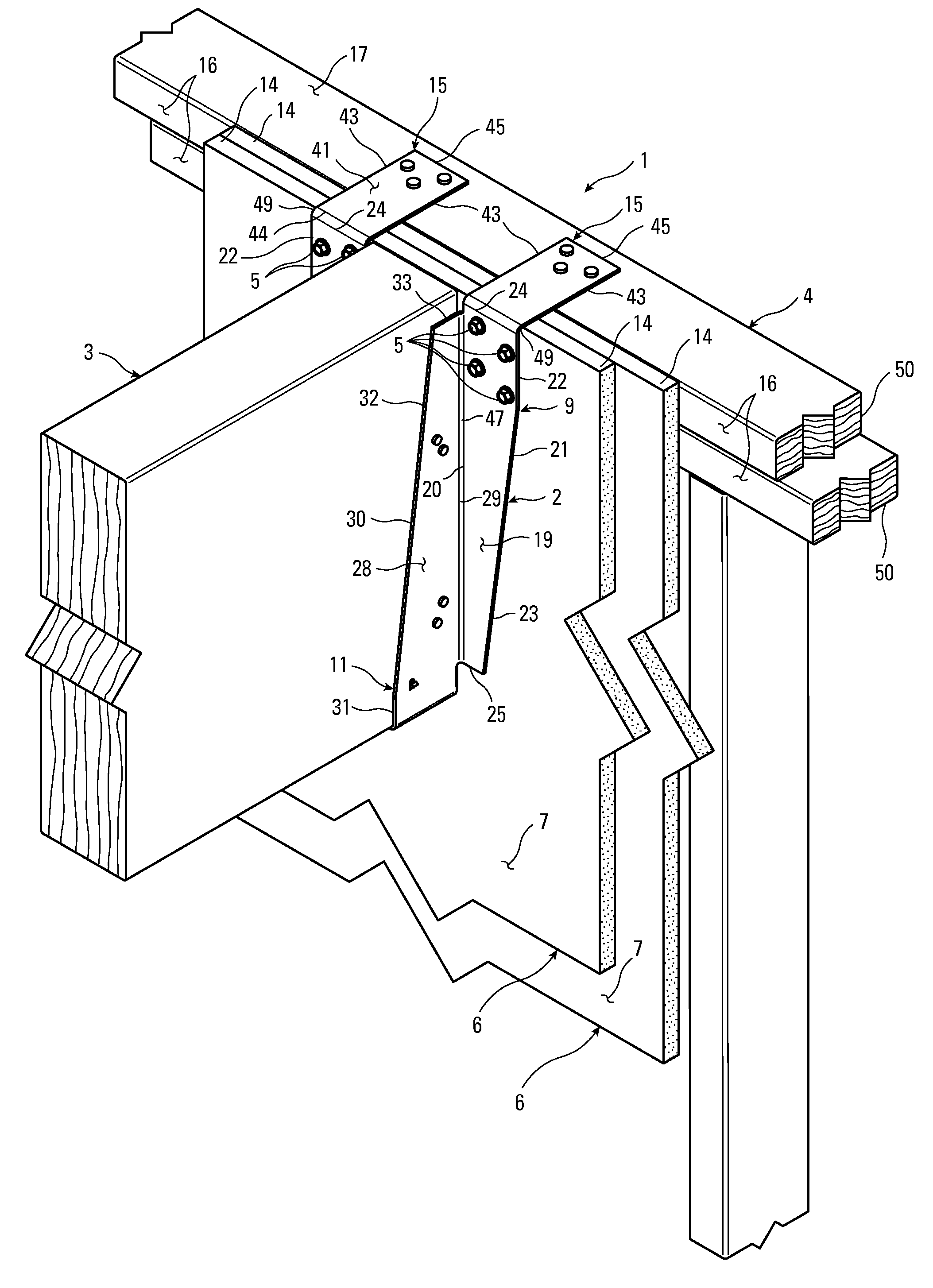
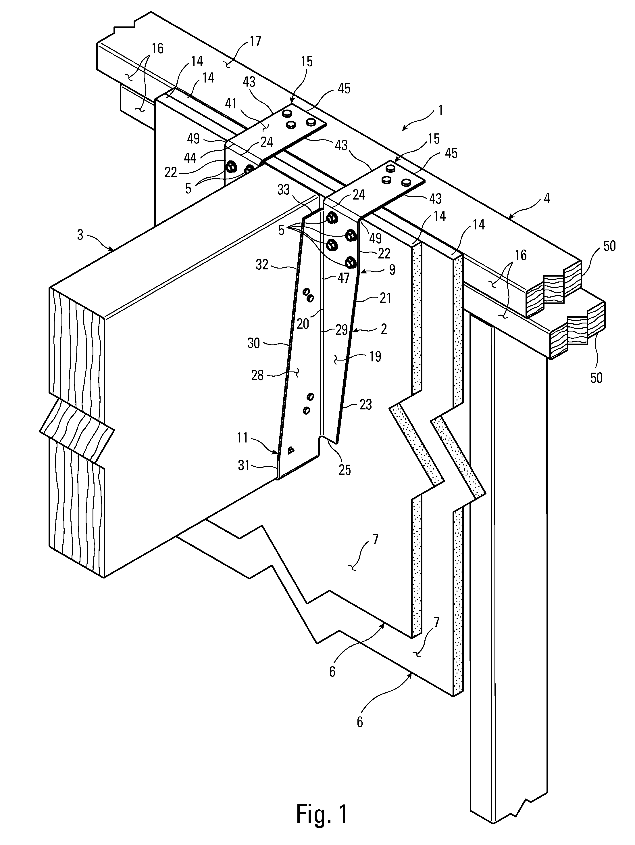
[0040]As shown in FIG. 1, the invention is a connection 1 utilizing a joist hanger 2 to hang a substantially horizontal joist 3 from a wood structural support member 4 in cooperation with a first plurality of fasteners 5 and one or more substantially vertical fire-resistant panels 6.

[0041]Preferably, the one or more fire-resistant panels 6 shield the wood structural support member 4, and each of the one or more fire-resistant panels 6 has a front face 7, a back face 8 opposite the front face 7, and negligible dowel bearing strength. While not shown in the drawings to show the vertically disposed studs and top plate 4 that makes up the wall, the panels 6 cover all of the structural wood members that make up the wall to protect them from fire.

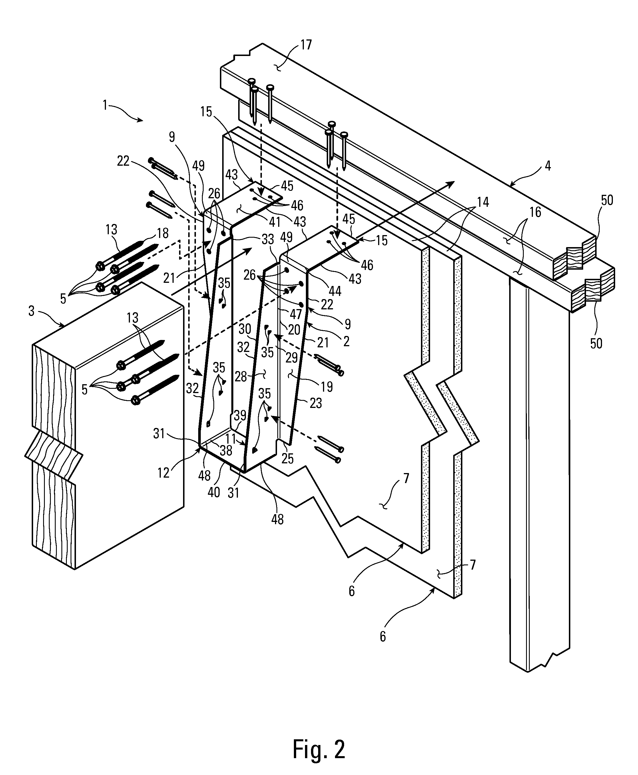
[0042]As shown in FIGS. 2 and 3, each fastener 5 preferably has a shank 13. Preferably, the structural support member 4 has a substantially vertical front face 16 and significant dowel bearing strength. The joist hanger 2 preferably supports the ...


PUM


Abstract

A connection utilizing a joist hanger to hang a substantially horizontal joist or beam from a wood structural support member such as a top plate or header in cooperation with a first plurality of fasteners such as screws and one or more substantially vertical fire-resistant panels such as drywall.

Description

FIELD OF INVENTION[0001]The present invention relates to building construction and, more particularly, to a joist hanger adapted to secure a joist to a header or other support member with a first drywall panel between the back of the joist hanger and the front of the header. This allows the first drywall panel, which is relatively incombustible, to extend up far enough to cover the front surface of the header.BACKGROUND[0002]Joist hangers are used in building construction to secure the ends of joists or other members to headers or other support members. Typically, the joist hanger includes a u-shaped portion that receives the joist. The bottom surface of the joist rests on the seat of the hanger, and the side walls of the hanger are dimensioned to closely receive the side faces of the joist, providing it with lateral support.[0003]Where appropriate, the joist may be connected to the hanger by means of nails driven through the side walls into the side faces of the joist. These nails ...

Claims


Application Information

Patent Timeline
IPC IPC(8): E04B1/26
CPCE04B1/2612E04B5/12E04B1/26E04B1/94
Inventor BUNDY, GREGORY D.MUHN, DUSTIN P.EVANS, THOMAS G.GRAY, DANIEL M.
Owner SIMPSON STRONG TIE
Why Eureka
Try Eureka