

Near Infrared Lens Assembly
- Summary
- Abstract
- Description
- Claims
- Application Information
AI Technical Summary
Benefits of technology
Problems solved by technology
Method used
Image

Examples
first embodiment
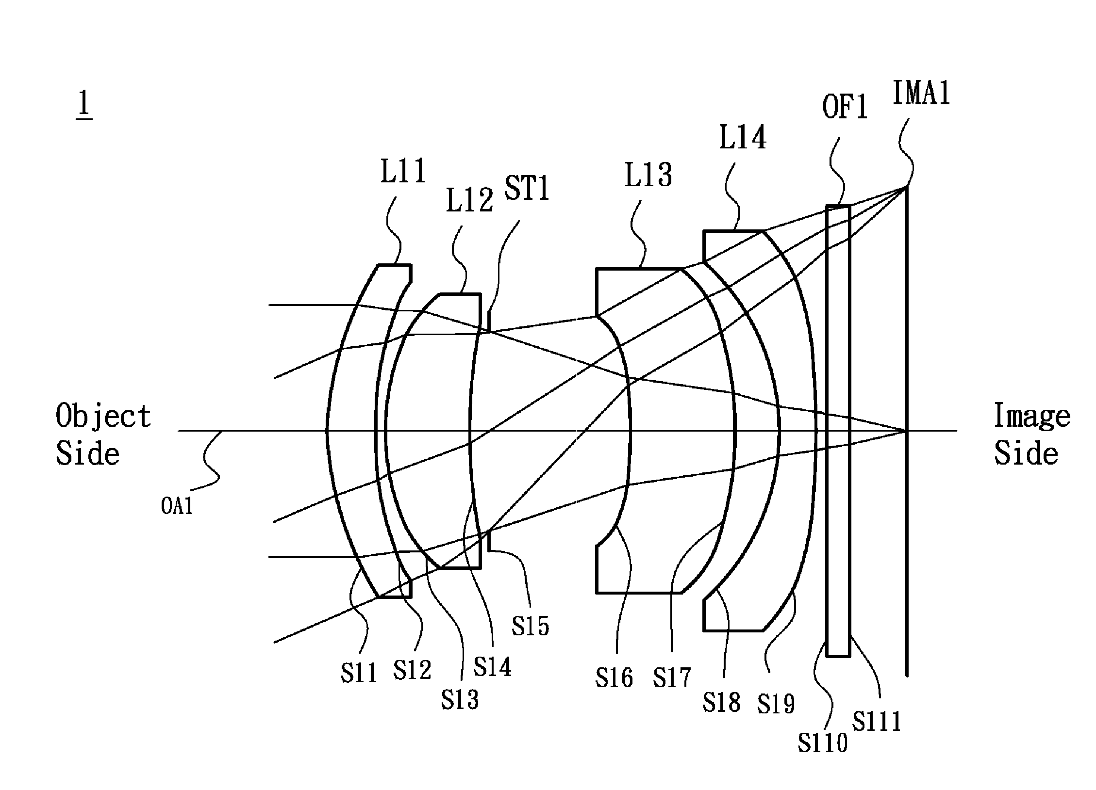
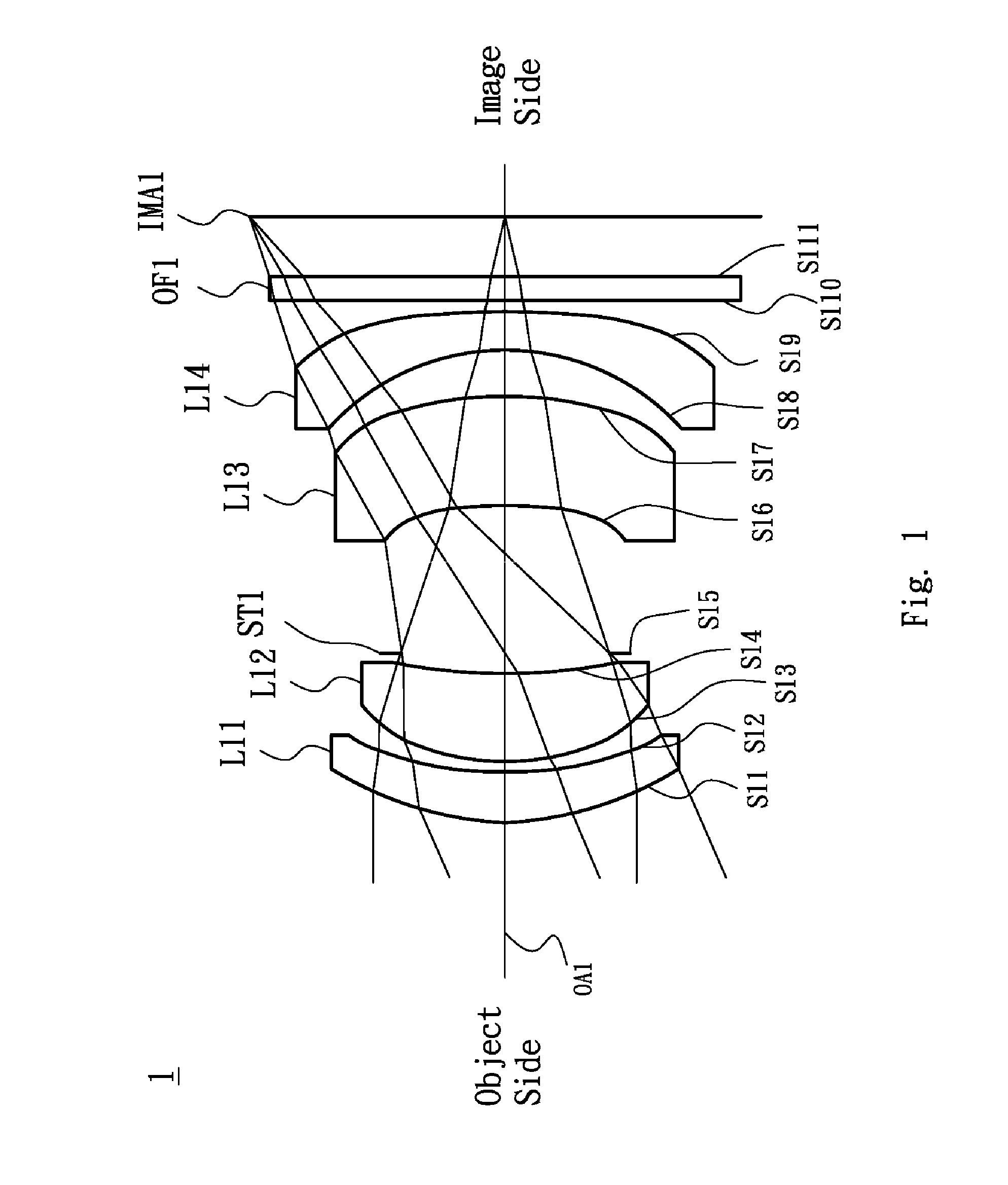
[0032]Referring to FIG. 1, FIG. 1 is a lens layout and optical path diagram of a near infrared lens assembly in accordance with the invention. The near infrared lens assembly 1 includes a first lens L11, a second lens L12, a stop ST1, a third lens L13, a fourth lens L14 and an Optical filter OF1, all of which are arranged in sequence from an object side to an image side along an optical axis OA1. In operation, an image of light rays from the object side is formed at an image plane IMA1. The first lens L11 is made of plastic material and with positive refractive power, wherein the object side surface S11 is a convex surface, the image side surface S12 is a concave surface and both of the object side surface S11 and image side surface S12 are aspheric surfaces. The second lens L12 is made of plastic material and with positive refractive power, wherein the object side surface S13 is a convex surface, the image side surface S14 is a concave surface and both of the object side surface S1...
second embodiment
[0042]Referring to FIG. 3, FIG. 3 is a lens layout and optical path diagram of a near infrared lens assembly in accordance with the invention. The near infrared lens assembly 2 includes a first lens L21, a second lens L22, a stop ST2, a third lens L23, a fourth lens L24 and an Optical filter OF2, all of which are arranged in sequence from an object side to an image side along an optical axis OA2. In operation, an image of light rays from the object side is formed at an image plane IMA2. The first lens L21 is made of plastic material and with positive refractive power, wherein the object side surface S21 is a convex surface, the image side surface S22 is a concave surface and both of the object side surface S21 and image side surface S22 are aspheric surfaces. The second lens L22 is made of plastic material and with positive refractive power, wherein the object side surface S23 is a convex surface, the image side surface S24 is a concave surface and both of the object side surface S2...
third embodiment
[0052]Referring to FIG. 5, FIG. 5 is a lens layout and optical path diagram of a near infrared lens assembly in accordance with the invention. The near infrared lens assembly 3 includes a first lens L31, a second lens L32, a stop ST3, a third lens L33, a fourth lens L34 and an Optical filter OF3, all of which are arranged in sequence from an object side to an image side along an optical axis OA3. In operation, an image of light rays from the object side is formed at an image plane IMA3. The first lens L31 is made of plastic material and with positive refractive power, wherein the object side surface S31 is a convex surface, the image side surface S32 is a convex surface and both of the object side surface S31 and image side surface S32 are aspheric surfaces. The second lens L32 is made of plastic material and with negative refractive power, wherein the object side surface S33 is a convex surface, the image side surface S34 is a concave surface and both of the object side surface S33...
PUM
 Abstract
Description
Claims
Application Information