Lens Assembly

Pending Publication Date: 2021-12-30
SINTAI OPTICAL SHENZHEN CO LTD +1
View PDF0 Cites 0 Cited by
  • Summary
  • Abstract
  • Description
  • Claims
  • Application Information

AI Technical Summary

Benefits of technology

The invention is a lens assembly that solves problems such as a shortened total lens length, decreased outer diameter, increased resolution, and ease of manufacturing while still maintaining good optical performance.

Problems solved by technology

The number of lenses used in the lens assembly for mobile phone is increasing, making the total length and outer diameter of the lens assembly for mobile phone is getting longer and larger and the ratio of the volume of the lens assembly to the internal volume of the mobile phone is also getting bigger, which can no longer meet the requirements of thin and light for mobile phone.

Method used


Image

  • Lens Assembly
  • Lens Assembly
  • Lens Assembly

Examples


first embodiment

[0057]In the first embodiment, the conic constant k and the aspheric coefficients A, B, C, D, E, F, G, H, I, J, K, L of each aspheric lens are shown in Table 2.

TABLE 2SurfaceABCDEFNumberkGHIJKLS19−36.04416−6.4247E−02  5.6985E−02−2.5117E−02 5.7448E−03−2.3892E−04−1.1273E−04−1.4731E−05  1.1584E−05−1.0947E−06−1.4817E−02−1.4010E−03−1.0969E−03S1102.66021.2024E−01−4.5800E−02 1.1232E−02−1.7176E−03−7.2719E−05 4.5098E−051.0977E−05−2.2770E−06−1.5996E−07−1.1107E−01 2.4481E−02−6.0939E−03S111−0.33789371.3195E−01−6.0139E−02 2.4629E−02−5.2884E−03 3.1803E−04−1.3230E−043.0679E−05 2.0153E−05−4.6069E−06−9.0329E−02 2.9799E−02−1.6650E−03S1121.034241−3.7632E−02  1.8802E−02−1.6136E−02 5.0841E−03−6.1590E−04−1.6311E−047.0473E−06 1.6313E−05−2.7390E−06 3.1593E−02 8.9310E−03 1.1042E−02S113−2.7848555.1219E−02−6.1254E−02 2.4460E−02−1.2739E−03−1.2216E−03 3.5027E−04−2.3110E−05 −1.3055E−05 2.1766E−06−7.7116E−02−8.7436E−03 6.8449E−04S114−4.2687649.7529E−02−1.0727E−01 3.0119E−02−8.9519E−04−3.0243E−03 9.8545E−049.6734E...

second embodiment

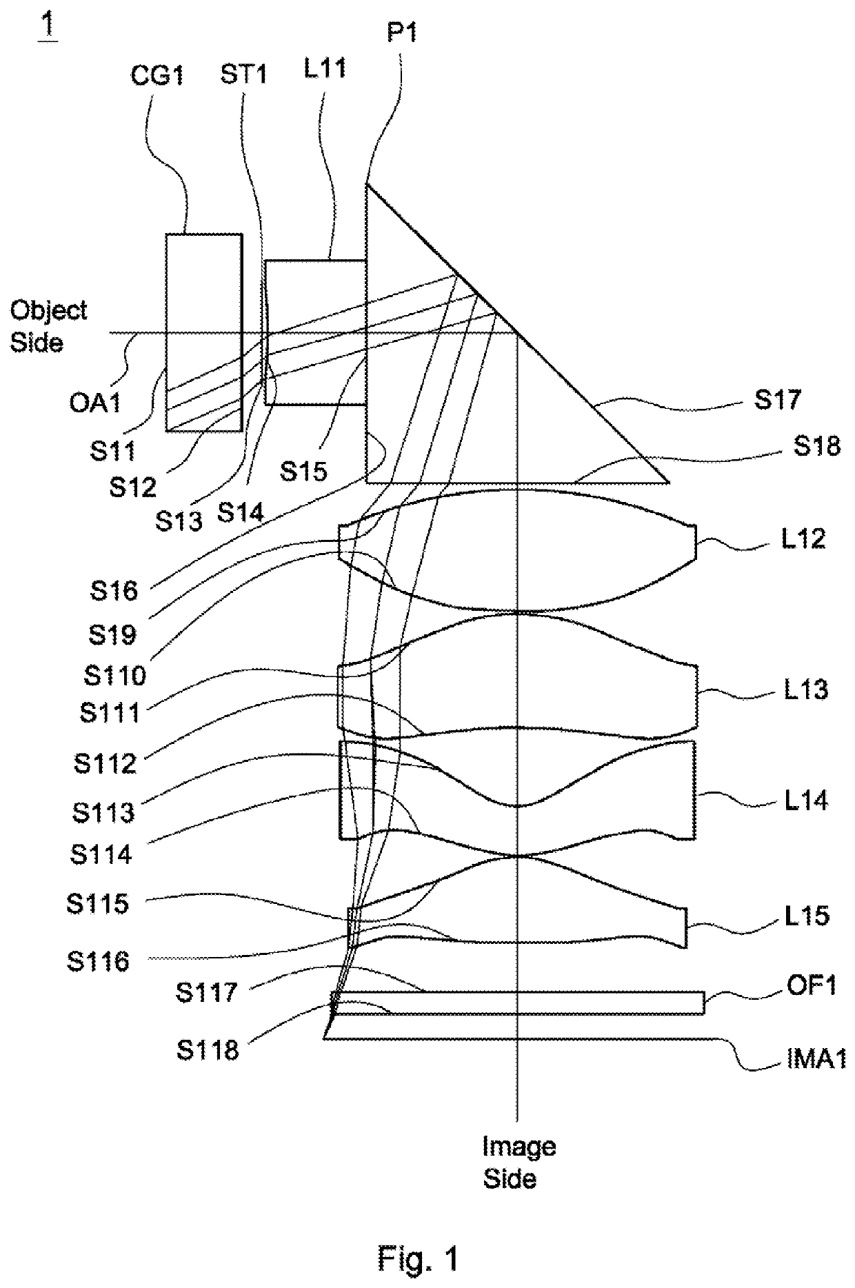
[0060]Referring to FIG. 3, the lens assembly 2 includes a cover glass CG2, a stop ST2, a first lens L21, a reflective element P2, a second lens L22, a third lens L23, a fourth lens L24, a fifth lens L25, and an optical filter OF2, all of which are arranged in order from an object side to an image side along an axis OA2. The reflective element P2 includes an incident surface S26, a reflective surface S27, and an exit surface S28, wherein the incident surface S26 and the exit surface S28 are perpendicular to each other. In operation, the light from the object side is reflected by the reflective surface S27 to change the propagation direction and imaged on an image plane IMA2. The image plane IMA2 and the exit surface S28 are parallel to each other. In the second embodiment, the reflective element takes a prism as an example but is not limited thereto. For example, the reflective element may be a reflective mirror which only includes a reflective surface.

[0061]According to paragraphs [...

third embodiment

[0068]Referring to FIG. 5, the lens assembly 3 includes a cover glass CG3, a stop ST3, a first lens L31, a reflective element P3, a second lens L32, a third lens L33, a fourth lens L34, a fifth lens L35, and an optical filter OF3, all of which are arranged in order from an object side to an image side along an axis OA3. The reflective element P3 includes an incident surface S36, a reflective surface S37, and an exit surface S38, wherein the incident surface S36 and the exit surface S38 are perpendicular to each other. In operation, the light from the object side is reflected by the reflective surface S37 to change the propagation direction and imaged on an image plane IMA3. The image plane IMA3 and the exit surface S38 are parallel to each other. In the third embodiment, the reflective element takes a prism as an example but is not limited thereto. For example, the reflective element may be a reflective mirror which only includes a reflective surface.

[0069]According to paragraphs [0...


PUM


Abstract

A lens assembly includes a first lens, a second lens, a third lens, a fourth lens, a fifth lens, and a reflective element. The first lens is with refractive power and includes a concave surface facing an object side along an axis. The second lens is with refractive power and includes a convex surface facing the object side along the axis. The third, fourth, and fifth lenses are with refractive power. The reflective element includes a reflective surface. The first, second, third, fourth, and fifth lenses are arranged in order from the object side to an image side along the axis. The reflective element is disposed between the first lens and the fifth lens. The lens assembly satisfies: 2 mm<L<6 mm; wherein L is an interval from an object side surface of the first lens to the reflective surface along the axis.

Description

BACKGROUND OF THE INVENTIONField of the Invention[0001]The invention relates to a lens assembly.Description of the Related Art[0002]The current development trend of a lens assembly for mobile phone is toward high resolution. The number of lenses used in the lens assembly for mobile phone is increasing, making the total length and outer diameter of the lens assembly for mobile phone is getting longer and larger and the ratio of the volume of the lens assembly to the internal volume of the mobile phone is also getting bigger, which can no longer meet the requirements of thin and light for mobile phone. Therefore, the lens assembly needs a new structure in order to meet the requirements of high resolution and miniaturization at the same time.BRIEF SUMMARY OF THE INVENTION[0003]The invention provides a lens assembly to solve the above problems. The lens assembly of the invention is provided with characteristics of a shortened total lens length, a decreased outer diameter, an increased r...

Claims


Application Information

Patent Timeline
IPC IPC(8): G02B13/00G02B9/60
CPCG02B13/0045G02B13/0065G02B9/60G02B13/0015
Inventor CHEN, CHIEN-HUNGCHANG, HSI-LINGWU, GUO-YANGCHEN, BO-YAN
Owner SINTAI OPTICAL SHENZHEN CO LTD
Why Eureka
Try Eureka