Method and Apparatus for Manufacturing Plastic Optical Fiber

Inactive Publication Date: 2008-11-13
FUJIFILM CORP +1
View PDF0 Cites 7 Cited by
  • Summary
  • Abstract
  • Description
  • Claims
  • Application Information

AI Technical Summary

Benefits of technology

[0018]According to the present invention, by controlling variation in the temperature in the heating furnace within ±0.5° C. to the set temperature by use of the orifices and the seal members, it is possible to decrease fluctuation in the outer diameter of the manufactured plastic optical fiber.

Problems solved by technology

As a result, the diameter of the POF to be drawn is also fluctuated, and thereby the optical property such as the optical transmission loss becomes worse.
Catching the POF by the nipple or the die causes the problem in the manufacture process and the quality of the manufactured POF.
Dividing the heating furnace to decrease turbulence of the temperature in the heating furnace is not sufficient in controlling the outer diameter of the POF.
The method described in JP-A No. 2003-171139 can shield the heating furnace from external air, but does not deal with the problem of fluctuation in temperature distribution in the heating furnace.
The core part of the preform is formed from acrylic resin in terms of the manufacture cost, however, the method as described in JP-A No. 8-334366 cannot be applied to manufacturing the POF of acrylic resin.
In PCT Publication WO / 40768, the material for the preform is limited to fluorine contained amorphous polymer without the C—H bond, so it is difficult to utilize the decompression condition in the hollow part of the preform, the regulations of the diameter ratio and the outer diameter, in manufacturing the acrylic POF.
Thus, when the acrylic POF is formed from the hollow cylindrical preform in order to reduce the manufacture cost, a void such as a bubble remained in the POF causes deterioration in the optical transmittance.

Method used


Image

  • Method and Apparatus for Manufacturing Plastic Optical Fiber
  • Method and Apparatus for Manufacturing Plastic Optical Fiber
  • Method and Apparatus for Manufacturing Plastic Optical Fiber

Examples


embodiment 1

[0036]A plastic optical fiber has a core part and a clad part both of which are formed from polymers. In the preferable embodiments, the POF (plastic optical fiber) is comprised of the core part and the clad part.

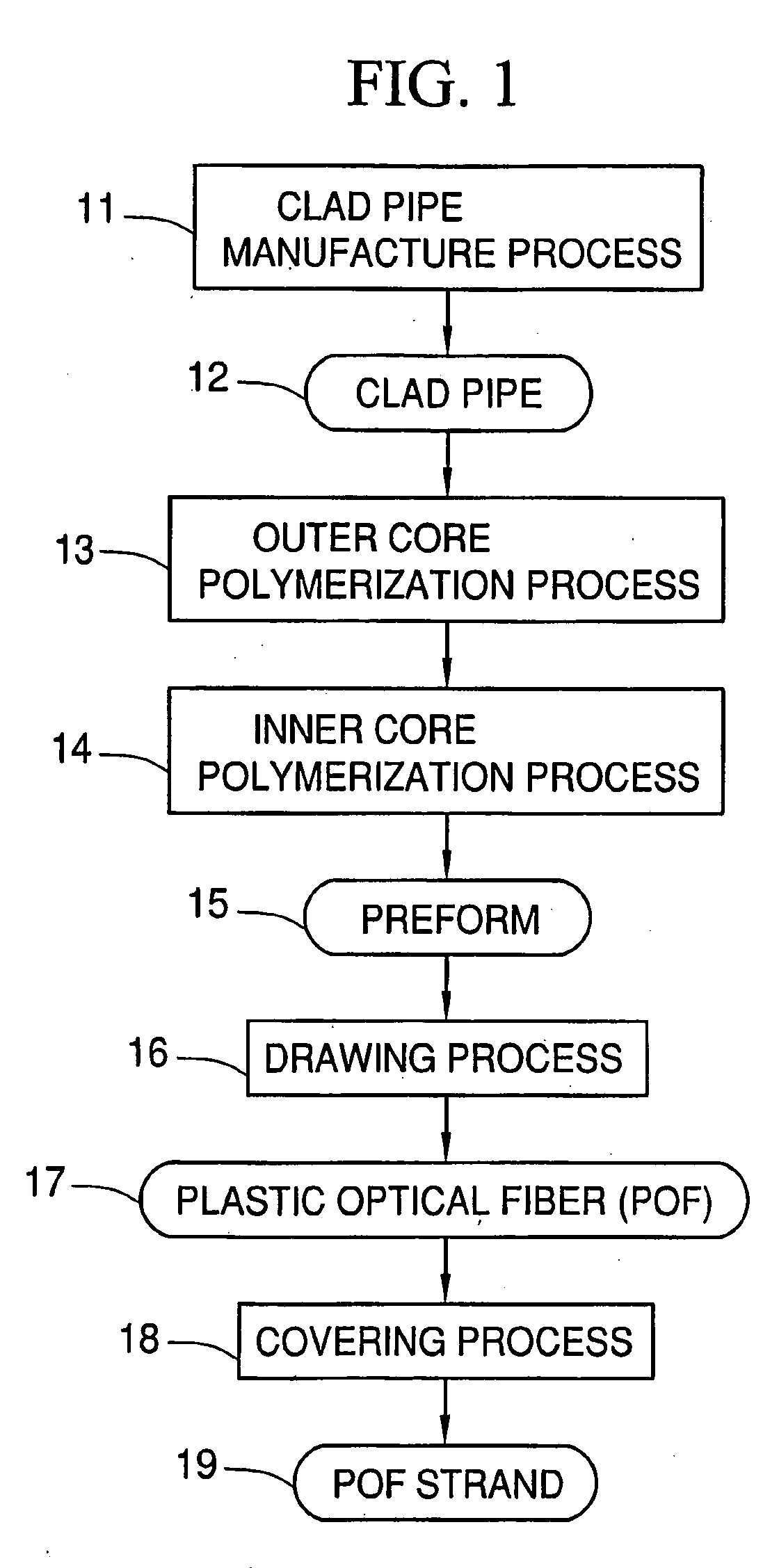
[0037]FIG. 1 is the flow chart of the manufacture method of the POF. In a clad pipe manufacturing process 11, a clad pipe 12 is produced by melt-extrusion of the polymers as the raw material. The clad pipe manufacturing process 11 will be described in detail. Then, in an outer core polymerization process 13, an outer core 20a (see FIG. 5A) is formed on the inner surface of the clad pipe 12. After preparing an outer core formation solution (outer core solution) including polymerizable composition, the outer core solution is poured into the clad pipe 12 to carry out polymerization of the outer core. Then, in an inner core polymerization process 14, an inner core 20b (see FIG. 5A) is formed in the outer core 20a. After preparing an inner core formation solution (inner core sol...

embodiment 2

[0168]In the above embodiment, the temperature in the heating furnace for melt-drawing process is controlled to reduce fluctuation in the diameter of the manufactured POF. In order to improve the quality of the POF, it is necessary to reduce the bubbles in the POF. Next, the manufacture method capable of reducing the bubbles in the POF is described. It is to be noted that, in Embodiment 2, the description about the structure of the POF (the core part and the clad part), the polymerization initiator, the chain transfer agent, the refractive index control agent, and the coating layer is the same as Embodiment 1, so the description about these elements are omitted. In addition, the first process to form the preform is the same as Embodiment 1, so the description about the first process is omitted.

[0169](Second Process)

[0170]In Embodiment 2, the core part (or the inner core part) is formed by the rotational gel polymerization in which the hollow pipe as the clad pipe is rotated and the ...


PUM

PropertyMeasurementUnit
Temperatureaaaaaaaaaa
Pressureaaaaaaaaaa
Pressureaaaaaaaaaa

Abstract

A preform (15) is hung from an arm (72) into a heating furnace (74). The heating furnace (74) has five heater units (90-94). A gas supply device (77) supplies nitrogen gas to the heating furnace (74). The heating furnace (74) is divided into five sections by orifices (95-100), and the temperature of each divided section is controlled by the heater units (90-94) provided in each section. A seal member (106) attached to the top side of the heating furnace (74) shields the heating furnace (74) from external air, so it is possible to prevent turbulence in the divided sections in the heating furnace (74).

Description

TECHNICAL FIELD[0001]The present invention relates to a method and an apparatus for manufacturing a plastic optical fiber.BACKGROUND ART[0002]Recent development in communication industry, the demand for the optical fiber with lower transmission loss and low manufacture cost has been increased. A plastic optical part has merits of design facility and low manufacture cost, compared with a glass optical part with identical structure. Especially, a plastic optical fiber (referred to as “POF”), entirely composed of a plastic material is suitable for manufacture of the optical fiber with large diameter at a low cost, because the POF has advantages in excellent flexibility, light weight and high machinability, compared with the glass optical fiber. Accordingly, it is planned to utilize the plastic optical fiber as an optical transmission medium for short-distance purpose in which the transmission loss is small (for example, Japanese Laid-Open Patent Publication (JP-A) No. 61-130904).[0003]...

Claims


Application Information

Patent Timeline
IPC IPC(8): B29D11/00G02B6/00G02B6/02
CPCB29D11/00721G02B6/02033G02B6/00
Inventor SATO, TAKANORINAKATA, SHUJIKEGASAWA, TADAHIROSHIROKURA, YUKIO
Owner FUJIFILM CORP
Why Eureka
Try Eureka