Display module and head up display

a display module and display module technology, applied in the field of optoelectronic devices, can solve the problems of reducing the volume of the display module and non-uniform display in the display module, and achieve the effect of favorable display

Active Publication Date: 2015-06-18
AU OPTRONICS CORP
View PDF2 Cites 9 Cited by
  • Summary
  • Abstract
  • Description
  • Claims
  • Application Information

AI Technical Summary

Benefits of technology

[0008]The embodiments of the invention are directed to a display module, which has a favorable displaying effect.
[0009]The embodiments of the invention are directed to a head up display, which has a favorable displaying effect.
[0012]Based on above, in the display module and the head up display according to an embodiment of the invention, the light converging elements of the light emitting units on different rows are spaced apart in up and down manner and in contact to each other. Therefore, arranging gap between the light converging elements of two adjacent light emitting unit rows may be reduced, so as to increase the area of the overlap region projected on the display panel by the illuminating beams emitted by the two. Accordingly, the brightness at the region where the two adjacent light emitting unit rows are intersected may be increased, so as to solve the problem of poor display in conventional art due to insufficient brightness at the region corresponding to where the two adjacent light emitting unit rows are intersected.

Problems solved by technology

As a divergence of the image beam gets greater, increase in a volume of the curved surface reflectors are required in order to effectively receive the image beam, which is disadvantageous in reducing the volume of the head up display.
However, each time after passing through the light converging element, the illuminating beam is focused towards an optical axis corresponding to the light source, thus the illuminating beam having insufficient brightness is received by a region of the display panel of the display module corresponding to intersections between multiple light converging elements (i.e., an edge of each of the light converging elements), resulting occurrence of non-uniform display in the display module.

Method used


Image

  • Display module and head up display
  • Display module and head up display
  • Display module and head up display

Examples


Embodiment Construction

[0038]Reference will now be made in detail to the present preferred embodiments of the invention, examples of which are illustrated in the accompanying drawings. Wherever possible, the same reference numbers are used in the drawings and the description to refer to the same or like parts.

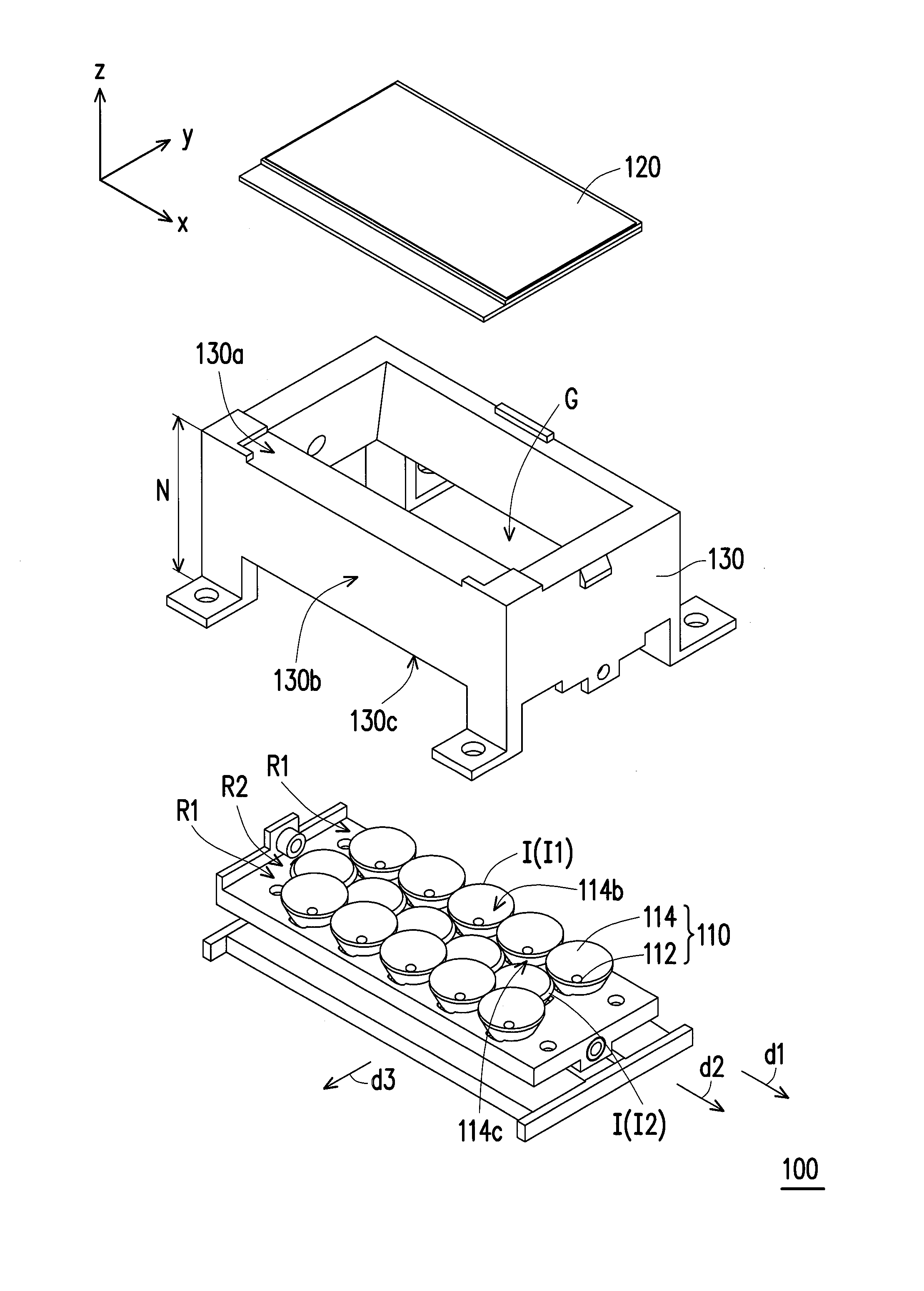
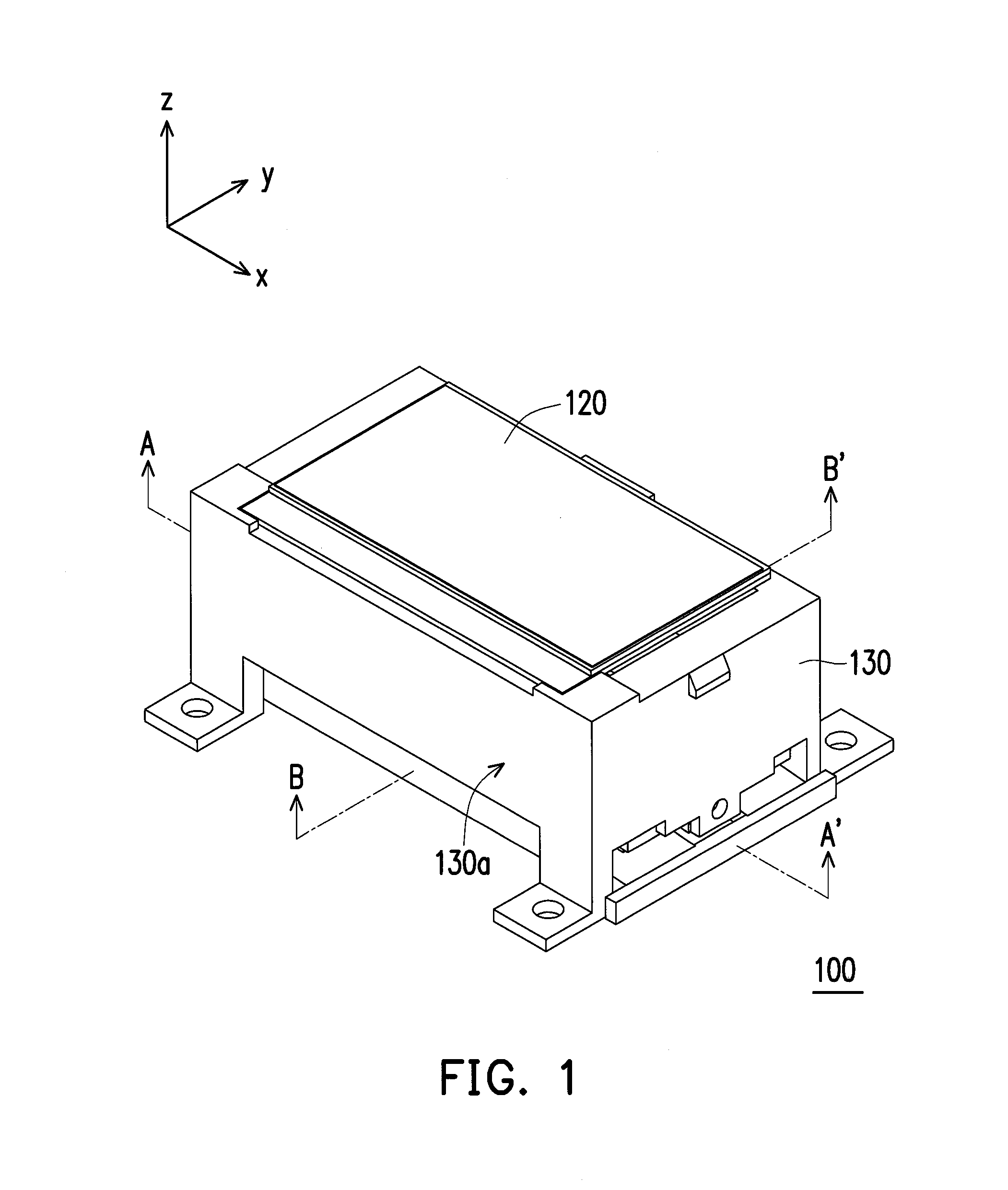
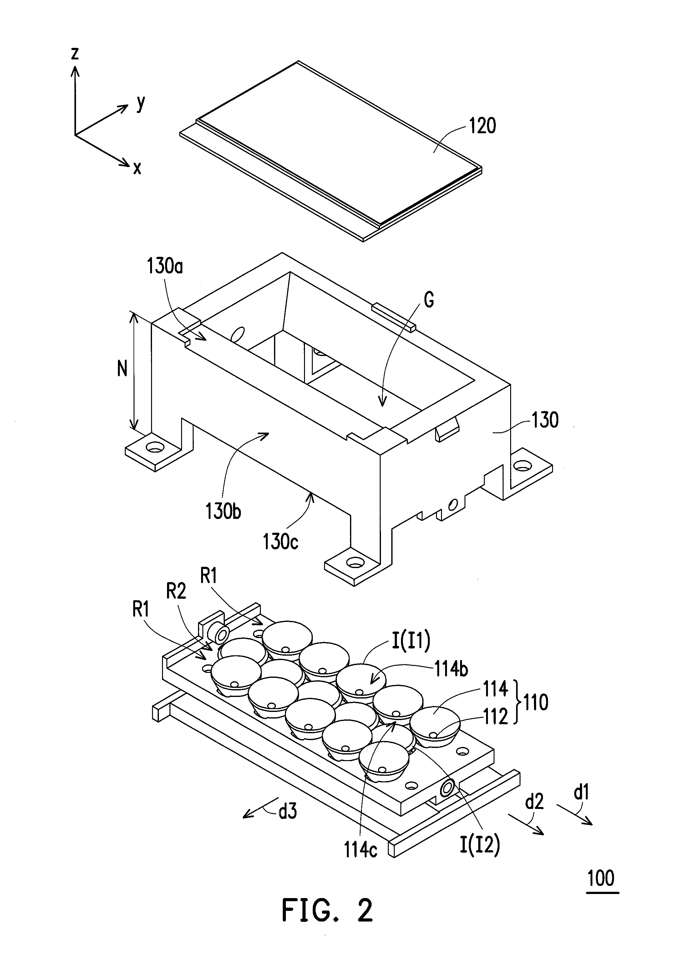
[0039]FIG. 1 is a three-dimensional diagram of a display module according to an embodiment of the invention. FIG. 2 is an explosion diagram of the display module depicted in FIG. 1. Referring to FIG. 1 and FIG. 2, a display module 100 of the present embodiment includes a plurality of light emitting units 110, and a display panel 120 disposed in a transmitting path of an illuminating beam L1 (marked in FIG. 3A) emitted by the light emitting unit 110. The display panel 120 may be of transitive or transflective types, based on actual requirements. In the present embodiment, the display panel 120 may be, for example, a liquid crystal display panel. However, the invention is not limited thereto. In other ...


PUM


Abstract

A display module including light emitting units and a display panel is provided. Each of the light emitting units includes a light source and a light converging element. The light emitting units are divided into at least one first light emitting unit row and a second light emitting unit row adjacent to the first light emitting unit row. Top surfaces of the light converging elements of the first light emitting unit row are disposed on a first surface. Top surfaces of the light converging elements of the second light emitting unit row are disposed on a second surface. The first surface is located between the display panel and the second surface. Moreover, a head up display including the display module is also provided.

Description

CROSS-REFERENCE TO RELATED APPLICATION[0001]This application claims the priority benefit of Taiwan application serial no. 102145903, filed on Dec. 12, 2013. The entirety of the above-mentioned patent application is hereby incorporated by reference herein and made a part of this specification.BACKGROUND[0002]1. Technical Field[0003]The invention disclosure relates to two optoelectronic devices, and more particularly to a display module and a head up display.[0004]2. Description of Related Art[0005]Head up displays are frequently applied to aircrafts as supplementary equipment of aviation. Some automobiles are also equipped with the head up displays, so as to project status data (e.g., car speed, rotation speed, engine coolant temperature, whether car doors are closed, mileage, fuel consumption, etc.) of the automobiles onto the windshields for drivers' reference.[0006]Generally, the head up display includes a display module and several curved surface reflectors. The curved surface re...

Claims


Application Information

Patent Timeline
Patent Type & Authority Applications(United States)
IPC IPC(8): G02B27/01
CPCG02B27/0101G02B27/0172G02B2027/015G02B2027/0161
Inventor NIU, TZU-LING
Owner AU OPTRONICS CORP
Why Eureka
Try Eureka