
System and method for multi-dimensional modeling of an industrial facility

a multi-dimensional modeling and industrial facility technology, applied in the field of industrial facilities, can solve the problems of requiring a significant amount of time and attention, requiring limited configuration and data, and difficult and tedious to identify problematic machine parameters or the location of a given machine or sensor

Active Publication Date: 2015-06-18
UPTIME SOLUTIONS LLC
View PDF6 Cites 42 Cited by
  • Summary
  • Abstract
  • Description
  • Claims
  • Application Information

AI Technical Summary

Benefits of technology

The present patent relates to a system for monitoring machine parameters in industrial facilities. The system uses sensors to detect machine parameters and a facility model to incorporate the sensor data into a virtual representation of the facility. The system provides a user interface to navigate through the facility model and monitor the status of the sensors. The technical effects of the patent include improved monitoring of machine parameters, reduced time and attention required for manual checks, improved identification and addressing of problematic machine parameters, and improved safety concerns. The system also allows for real-time monitoring and alerts based on sensor data, and provides user customization features.

Problems solved by technology

Often times these sensors have to be checked manually, requiring a significant amount of time and attention to physically check each machine or even each sensor in a given facility on a regular basis.
Some sensors are configured to sound an alarm when certain machine parameters have been detected as exceeding a threshold, but these alarms can be disruptive and provide limited configuration and data.
In some instances, the sensor data is collected and temporarily stored in a database so that it can be accessed in the form of a chart, which can be densely populated, making it difficult and tedious to identify problematic machine parameters or the location of a given machine or sensor, and requiring several steps of identification before a given problem can be assessed.
This inability to appropriately monitor and address machine parameters may lead to machine failure, inefficiencies, greater expense, and safety concerns.

Method used


Image

  • System and method for multi-dimensional modeling of an industrial facility
  • System and method for multi-dimensional modeling of an industrial facility
  • System and method for multi-dimensional modeling of an industrial facility

Examples


Embodiment Construction

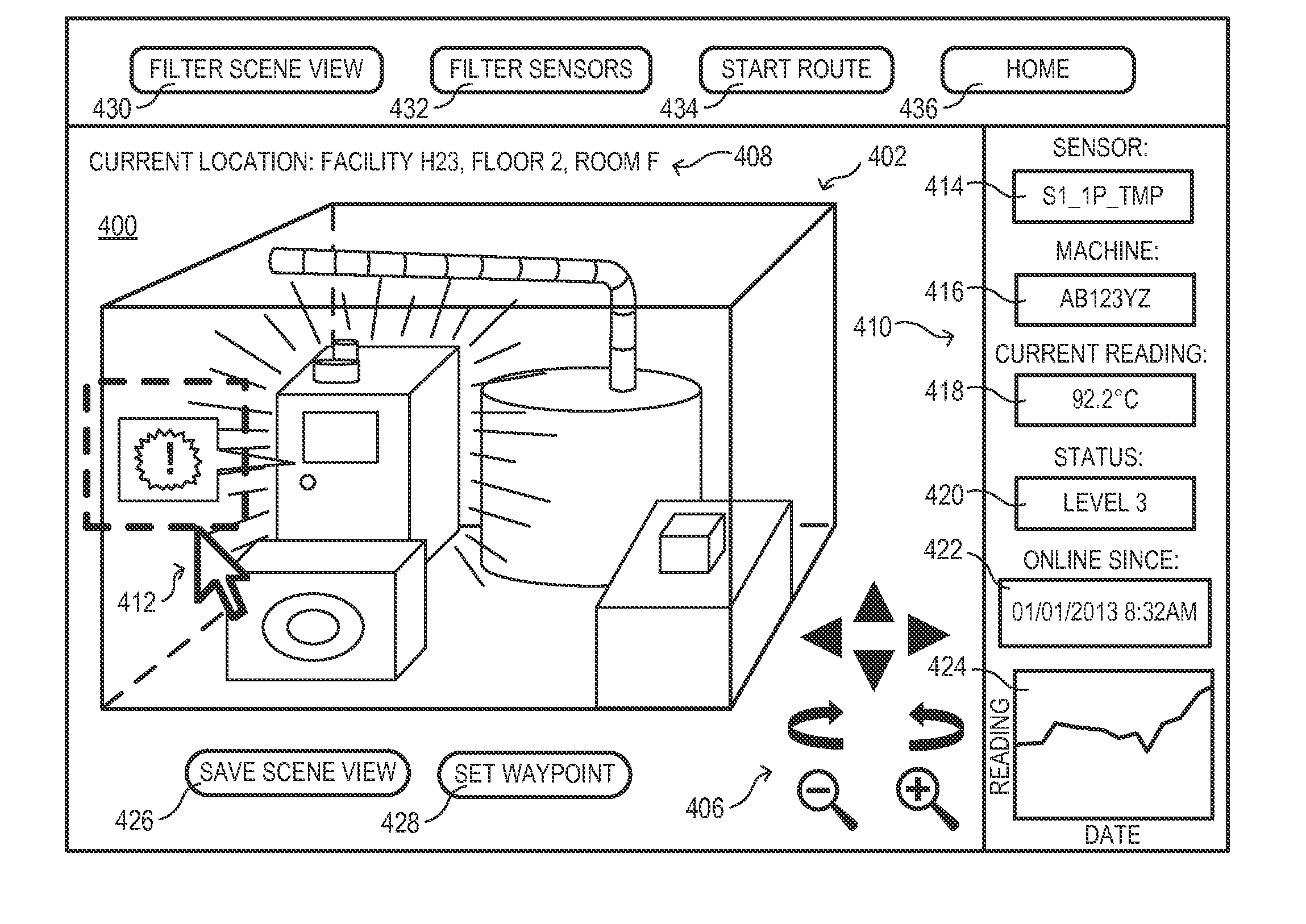
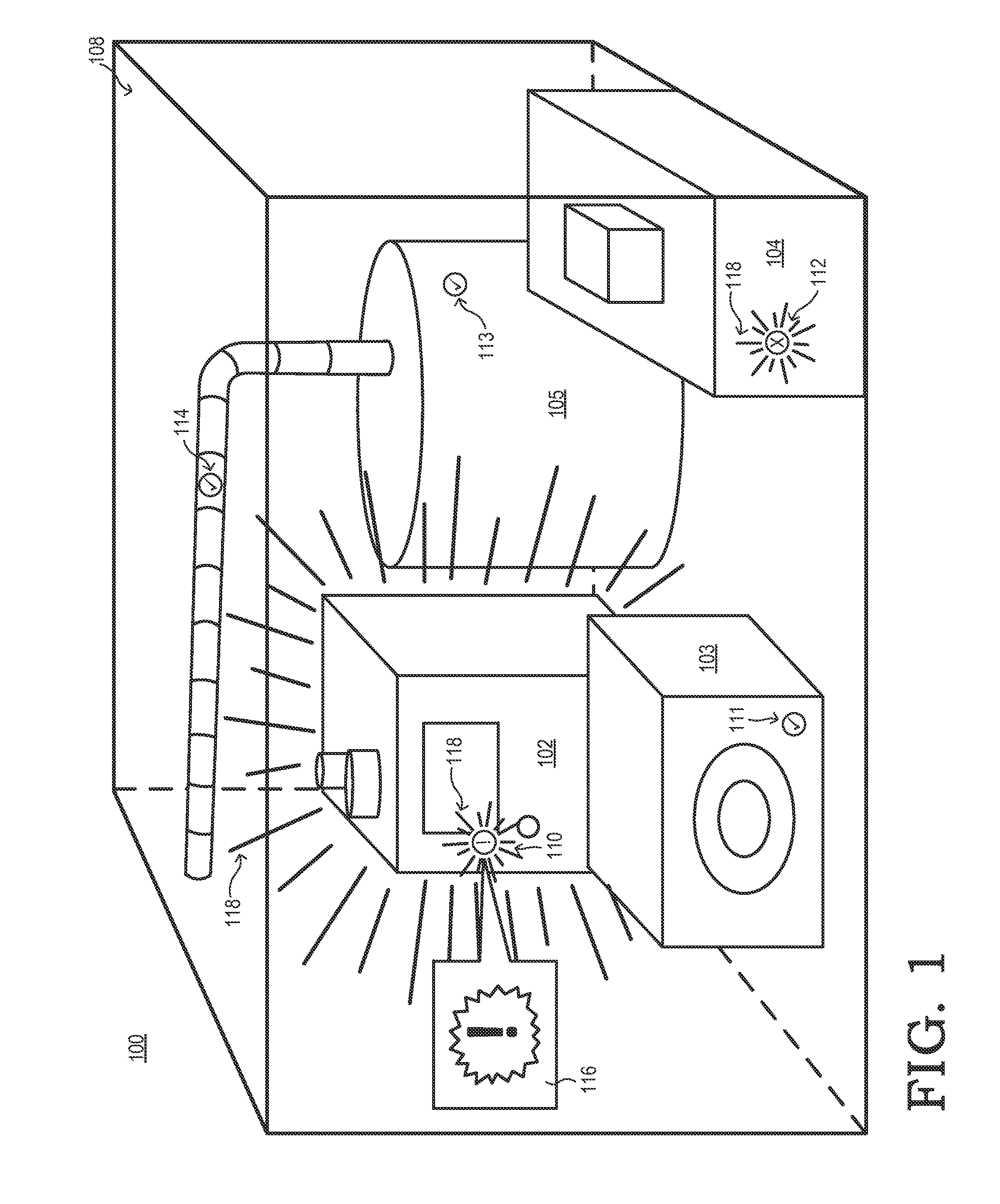
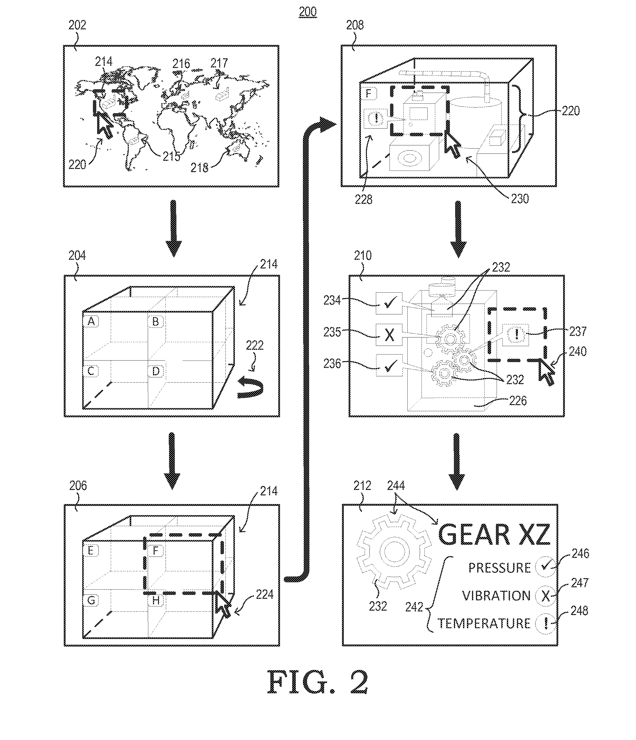
[0017]FIGS. 1-11 illustrate example implementations of a facility modeling system that renders graphical representations of machines and their environment within a facility to facilitate effective monitoring of machine parameters and health. A sensor control module communicates with a plurality of sensors detecting machine parameter data for machines housed in a facility (which itself may be a machine). The machine parameters may include, for example, temperature, vibration, stress, acceleration, velocity, pressure, liquid level, gas level, gas concentration, sound, electric field, speed, torque, displacement, and any other information that may directly or indirectly indicate the status of a machine or a part of a machine, or an environment in which a machine is located. The information collected from the sensors is incorporated into a facility model (a graphical rendering of the facility) which may be presented using any of a variety of multi-dimensional views, for example, two-dim...


PUM


Abstract

A facility modeling system renders graphical representations of machines and their environment in a facility model to facilitate monitoring of machine parameters and health. A sensor control module communicates with a plurality of sensors detecting machine parameter data for machines housed in a facility. The machine parameters may include any information that may directly or indirectly indicate the status of a machine or a part of a machine. The information collected from the sensors is incorporated into the facility model (a graphical rendering of the facility) which may provide any of a variety of multi-dimensional views of the facility. A GUI allows a user to navigate through the facility model to identify and monitor the status of the sensors. The sensor status may be indicated by an icon, callout, change in a display characteristic of a facility, machine, part, space, or item, a combination of these, and the like.

Description

BACKGROUND[0001]1. Field of the Disclosure[0002]The present disclosure relates generally to industrial facilities and, more particularly, to monitoring of machine parameters in industrial facilities.[0003]2. Description of the Related Art[0004]Industrial facilities, such as manufacturing facilities, laboratories, research facilities, refineries, and the like, require constant monitoring of machine parameters to ensure that the machines will continue to work properly. In many cases each machine, room, or area is equipped with one or more sensors that monitor machine parameters. Often times these sensors have to be checked manually, requiring a significant amount of time and attention to physically check each machine or even each sensor in a given facility on a regular basis. Some sensors are configured to sound an alarm when certain machine parameters have been detected as exceeding a threshold, but these alarms can be disruptive and provide limited configuration and data. In some in...

Claims


Application Information

Patent Timeline
Patent Type & Authority Applications(United States)
IPC IPC(8): G06F3/0484G06F3/0481
CPCG06F3/04842G06F3/04815G06F3/04817G06F3/0484G06Q50/04G06T11/00G06F3/04847Y02P90/30G05B23/0216
Inventor GIRARDEAU, JAMES
Owner UPTIME SOLUTIONS LLC
Learn More