System and method for performing vision system planar hand-eye calibration from straight line features

a technology of vision system and straight line features, applied in the field of calibration systems and methods, can solve the problems of increasing cost and setup time, and achieve the effect of reducing the dependence of the vision system and sufficient calibration accuracy

Active Publication Date: 2015-06-18
COGNEX CORP
View PDF7 Cites 15 Cited by
  • Summary
  • Abstract
  • Description
  • Claims
  • Application Information

AI Technical Summary

Benefits of technology

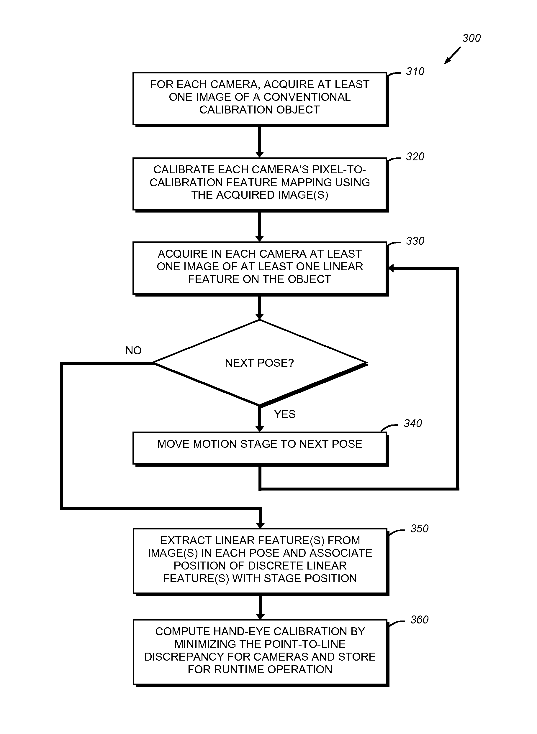
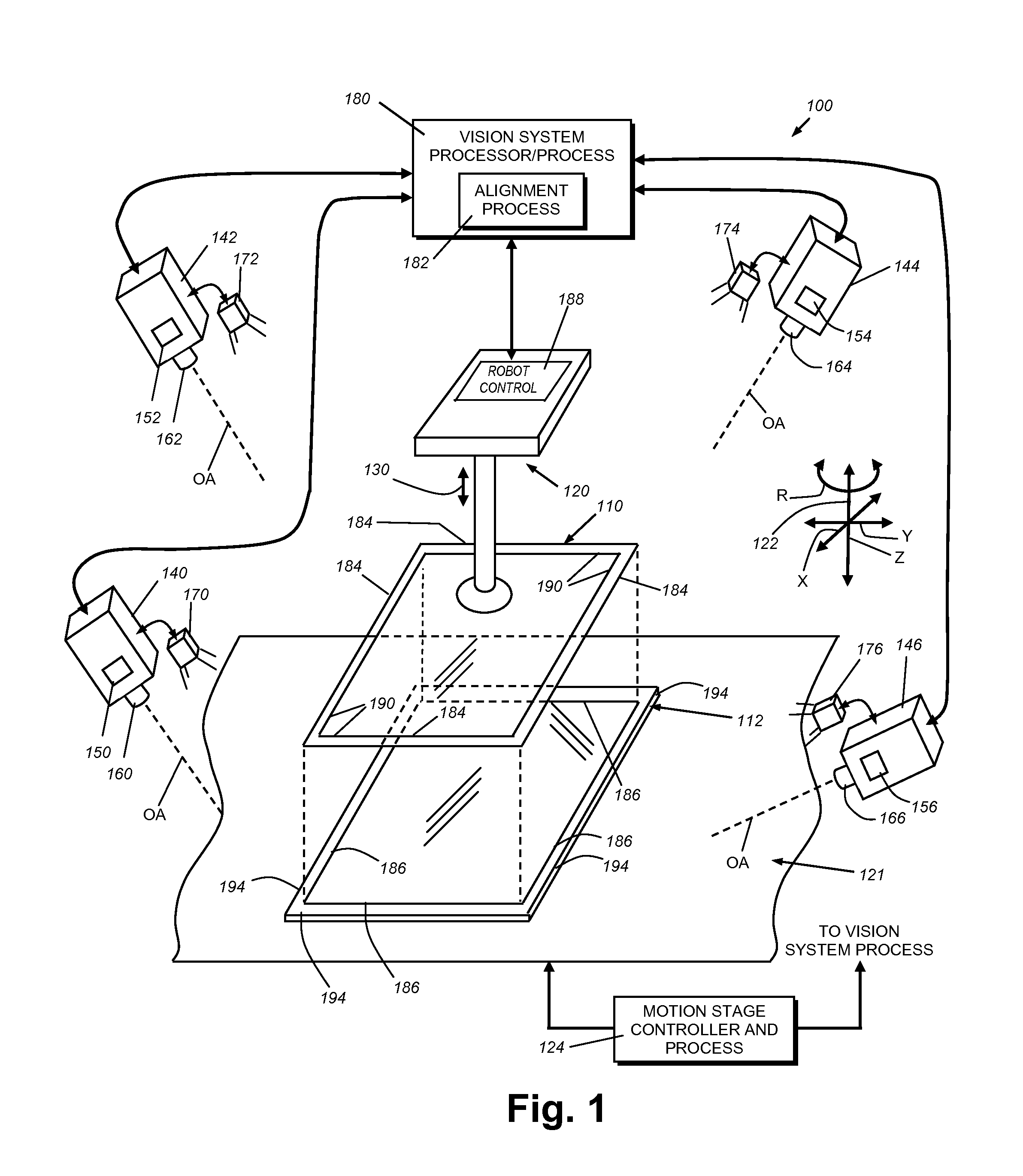
[0010]This invention overcomes disadvantages of the prior art by providing a system and method for performing planar (i.e. 2D) hand-eye calibration by moving a typical (runtime) work piece, which the underlying part / object handling device (e.g. a robot manipulator and / or motion stage) is designed to handle during its intended, runtime manufacturing process. The system and method reduces a vision system's reliance on a special calibration target during hand-eye calibration. Specifically, the illustrative embodiments enable the performance of hand-eye calibration by viewing only one or more straight line features on an object / work piece during stage motion. This system and method can desirably achieve a sufficient level of calibration accuracy for a wide range of vision system applications. The system and method illustratively performs hand-eye calibration by viewing only one or more straight line features on the work piece during stage motion, and using these features to establish a coordinate system for use as a reference by the vision system. This system and method can be applied to single-camera arrangements or a multiple camera arrangement using a single, global (and / or motion) coordinate system

Problems solved by technology

The standard technique for machine vision hand-eye calibration, for example in the above-described cover-glass mounting arrangement, which requires the movement of a special calibration target (e.g., a checkerboard calibration plate), can be cumbersome for operational reasons (e.g., spatial constraints in the work volume, special mounting fixture and / or gripper for holding the target).
This can entail the use of custom designed calibration plates and / or fixtures that increase cost and setup time.

Method used


Image

  • System and method for performing vision system planar hand-eye calibration from straight line features
  • System and method for performing vision system planar hand-eye calibration from straight line features
  • System and method for performing vision system planar hand-eye calibration from straight line features

Examples


Embodiment Construction

I. Hand-Eye Calibration, Further Considerations

[0020]Traditional hand-eye calibration, whether performed manually, or within a vision system, entails establishing correspondence between observed image feature positions and their expected physical positions, and minimizing the discrepancy between the observed positions and the expected positions. In the illustrative embodiment, the use of linear features, and the like, employs various aspects of traditional hand-eye calibration, but additional considerations are addressed. These considerations arise because of the differences between the calibration features available in traditional hand-eye calibration as performed in the prior art and the novel approach to calibration using runtime objects of manufacture and selected linear features thereon. These differences relate primarily to the type of correspondence, which in turn, results in different ways to compute and minimize the discrepancy between the observed data in the acquired imag...


PUM


Abstract

This invention provides a system and method for hand-eye calibration of a vision system using an object under manufacture having at least one feature. The feature can be a linear feature and the object moves in at least one degree of freedom in translation or rotation on a motion stage. The system further comprises at least a first vision system camera and vision processor. The first vision system camera is arranged to acquire an image of the first linear feature on the object under manufacture and to track motion of the first linear feature in response to moving of the motion stage in at least one degree of translation. The first linear feature is identified in at least two different positions along a plane. The system computes a mapping between pixel positions in a pixel coordinate system of the first camera and physical positions in a motion coordinate system based upon locations of the at least two positions.

Description

FIELD OF THE INVENTION[0001]The present invention relates to calibration systems and methods, and calibration objects used in machine vision system applications.BACKGROUND OF THE INVENTION[0002]In machine vision systems (also termed herein “vision systems”), one or more cameras are used to perform vision system process on an object or surface within an imaged scene. These processes can include inspection, decoding of symbology, alignment and a variety of other automated tasks. More particularly, a vision system can be used to inspect a flat work piece passing through an imaged scene. The scene is typically imaged by one or more vision system cameras that can include internal or external vision system processors that operate associated vision system processes to generate results. It is generally desirable to calibrate one or more cameras to enable it / them to perform the vision task(s) with sufficient accuracy and reliability. A calibration plate can be employed to calibrate the camer...

Claims


Application Information

Patent Timeline
Patent Type & Authority Applications(United States)
IPC IPC(8): G06T7/00G06K9/32G06T7/20
CPCG06T7/0018G06T7/2033G06T7/0004G06K9/3241G06T2207/10016G06T2207/30108G06T2207/30204G06T7/80G01C21/00G06T2207/30244
Inventor LIU, GANG
Owner COGNEX CORP
Why Eureka
Try Eureka