Apparatus for cleaning fluid

Inactive Publication Date: 2015-06-25
SEOUL VIOSYS CO LTD
View PDF4 Cites 10 Cited by
  • Summary
  • Abstract
  • Description
  • Claims
  • Application Information

AI Technical Summary

Benefits of technology

[0009]Since an apparatus for cleaning a fluid of the present invention may have high sterilization and deodorization effects by emitting light having a plurality of wavelength bands and may improve filter reuse efficiency using a filter on which a photocatalyst is coated, the filter

Problems solved by technology

Nowadays, most people live in cities, and most cities are contaminated with various contaminants discharged from automobiles, industries, etc.
The filter method has a problem in that since the air cleaning filter has to be periodically replaced, maintenance costs are continuously incurred.
Also, the filter method has problems in that when cleaning is not periodically performed or the air cleaning filter is not periodically replaced, bacteria may propagate in the air cleaning filter and the contaminants ma

Method used


Image

  • Apparatus for cleaning fluid
  • Apparatus for cleaning fluid
  • Apparatus for cleaning fluid

Examples


first embodiment

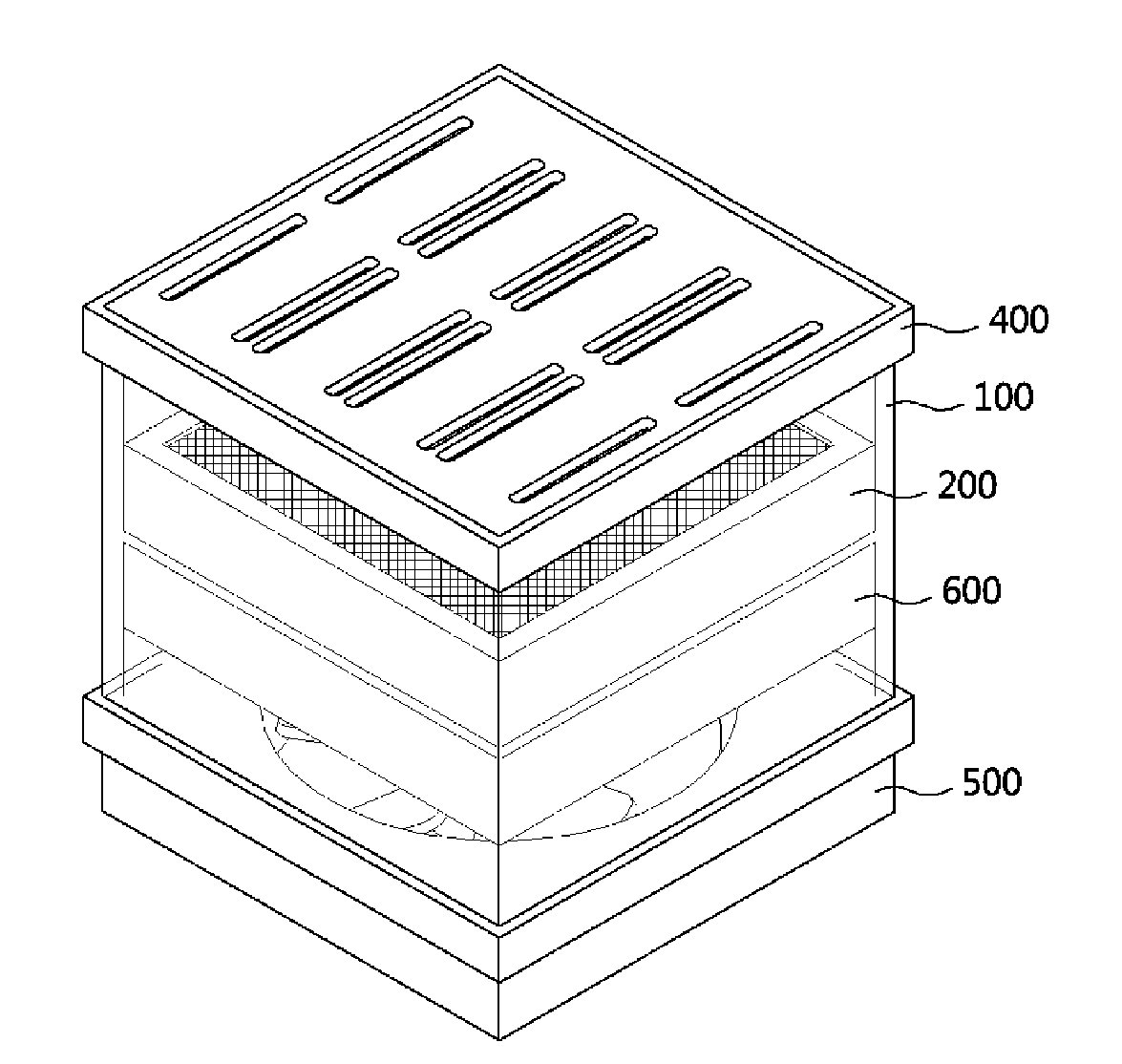
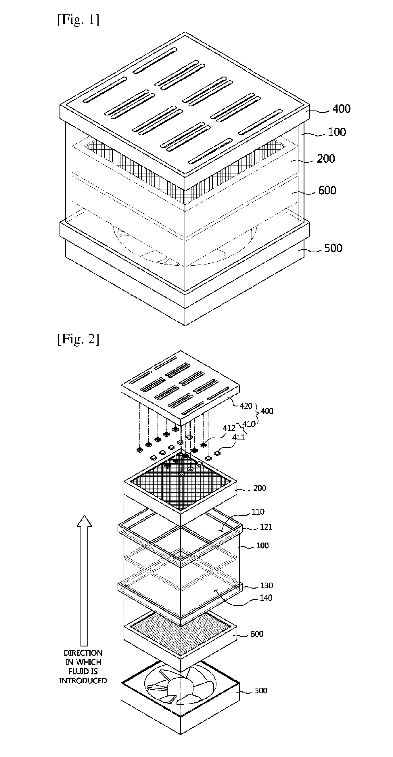
[0022]FIGS. 1 and 2 are a perspective view and an exploded perspective view illustrating an apparatus for cleaning a fluid, according to a first embodiment of the present invention, respectively.

[0023]Referring to FIGS. 1 and 2, the apparatus according to the first embodiment includes an outer case 100, a fluid cleaning filter 200, and a first light source unit 400. As shown in FIG. 1, the fluid cleaning filter 200 is received in the outer case 100, and filters the fluid introduced into the outer case 100. A photocatalyst 300 is coated on a surface of the fluid cleaning filter 200. The first light source unit 400 emits light toward a photocatalyst-coated surface of the fluid cleaning filter 200. The light emitted by the first light source unit 400 toward the photocatalyst-coated surface of the fluid cleaning filter 200 activates the photocatalyst 300 coated on the surface of the fluid cleaning filter 200, and contaminants adsorbed onto the fluid cleaning filter 200 are decomposed du...

second embodiment

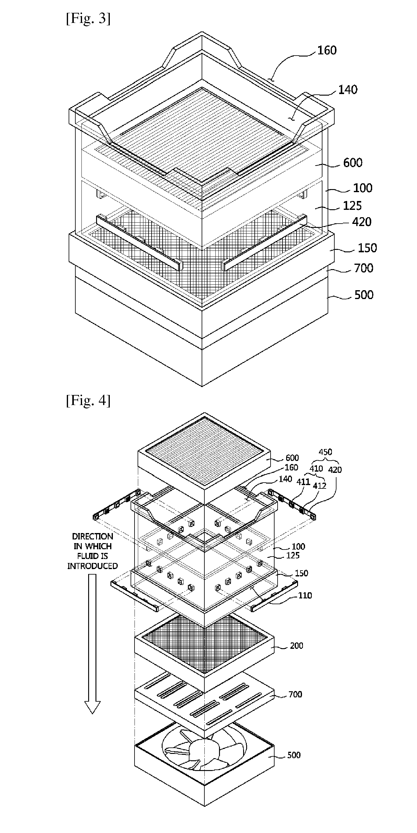
[0039]FIGS. 3 and 4 are a perspective view and an exploded perspective view illustrating an apparatus for cleaning a fluid, according to a second embodiment of the present invention, respectively.

[0040]The apparatus according to the second embodiment of FIGS. 3 and 4 may be embodied as a separate apparatus for cleaning a fluid from the apparatus of the first embodiment, or may be embodied by adding a structure of a second light source unit 450 to the apparatus of the first embodiment. The following explanation will be given under the assumption that the apparatus is embodied as a separate apparatus from the apparatus of the first embodiment, but the scope of the second embodiment is not limited thereto.

[0041]Referring to FIGS. 3 and 4, the apparatus according to the second embodiment includes the outer case 100, the fluid cleaning filter 200, and a second light source unit 450. The outer case 100 is a space where the fluid to be cleaned, that is, the fluid including the contaminants...


PUM

PropertyMeasurementUnit
Wavelengthaaaaaaaaaa

Abstract

Provided is an apparatus for cleaning a fluid using an ultraviolet light-emitting diode. The apparatus includes an outer case, a fluid cleaning filter disposed in the outer case and filters the fluid introduced, a photocatalyst coated on a surface of the fluid cleaning filter, and a first light source unit mounted on the outer case to face a rear surface of the fluid cleaning filter in a direction in which the fluid is introduced, and emits light having a plurality of wavelength bands toward the rear surface of the fluid cleaning filter. Since the apparatus may have high sterilization and deodorization effects by emitting light having a plurality of wavelength bands and may improve filter reuse efficiency using a filter on which a photocatalyst is coated, the filter may be semi-permanently used and fluid cleaning efficiency may be improved.

Description

TECHNICAL FIELD[0001]The present invention relates to an apparatus for cleaning a fluid, and more particularly, to an apparatus for cleaning a fluid using an ultraviolet light-emitting diode.BACKGROUND ART[0002]Nowadays, most people live in cities, and most cities are contaminated with various contaminants discharged from automobiles, industries, etc. In particular, contaminants included in yellow dust blown from China pass over the Pacific Ocean and reach as far as the western part of the U.S. Since the contaminants may cause various diseases as well as respiratory ailments such as a bronchial trouble, it is necessary to remove the contaminants.[0003]A representative method from among methods of removing such contaminants in the air is an air cleaning filter method using an air cleaning filter. The filter method has a problem in that since the air cleaning filter has to be periodically replaced, maintenance costs are continuously incurred. Also, the filter method has problems in th...

Claims


Application Information

Patent Timeline
IPC IPC(8): B01D53/88A61L2/08A61L9/20B01D53/86
CPCB01D53/885B01D53/8678A61L2/088A61L9/205B01D2255/802B01D2255/40B01D2259/804B01D2255/20776B01D2255/20792B01D2258/06B01D2257/91B01D2257/708B01D2255/20707A61L2/10A61L9/20A61L2209/14B01D53/8668B01D2259/4508B01D2259/802A61L9/18B01D53/02B01D53/34B01D53/86
Inventor SON, YOUNG HWANSUH, DAEWOONGLEE, SEONG MIN
Owner SEOUL VIOSYS CO LTD
Why Eureka
Try Eureka