Stairwell lift

Active Publication Date: 2015-06-25
LIN CHEN HSIN
View PDF14 Cites 2 Cited by
  • Summary
  • Abstract
  • Description
  • Claims
  • Application Information

AI Technical Summary

Benefits of technology

The stairwell lift in this patent is designed to fit the dimensions of the stairway and sliding portions, making it wide and comfortable for passengers. It also effectively protects the safety of passengers.

Problems solved by technology

This causes certain troubles to the elderly or the disabled people.
The lift that requires a lift shaft often occupies an excessive amount of space and the installation may requires damages made on the building and the subsequent maintenance expenditure is high.
The stairwell lift can be installed without concerns about constrained imposed by the limited space, but the stairway lift, when moving upwards along the rail, is readily susceptible to vibration and shaking and may thus cause concerns of safety.
In addition, the stairway lift and the rail often need to occupy a major part of the space of the stairway, making it inconvenient to walk or to carry articles through the stairway.

Method used


Image

  • Stairwell lift
  • Stairwell lift
  • Stairwell lift

Examples


first embodiment

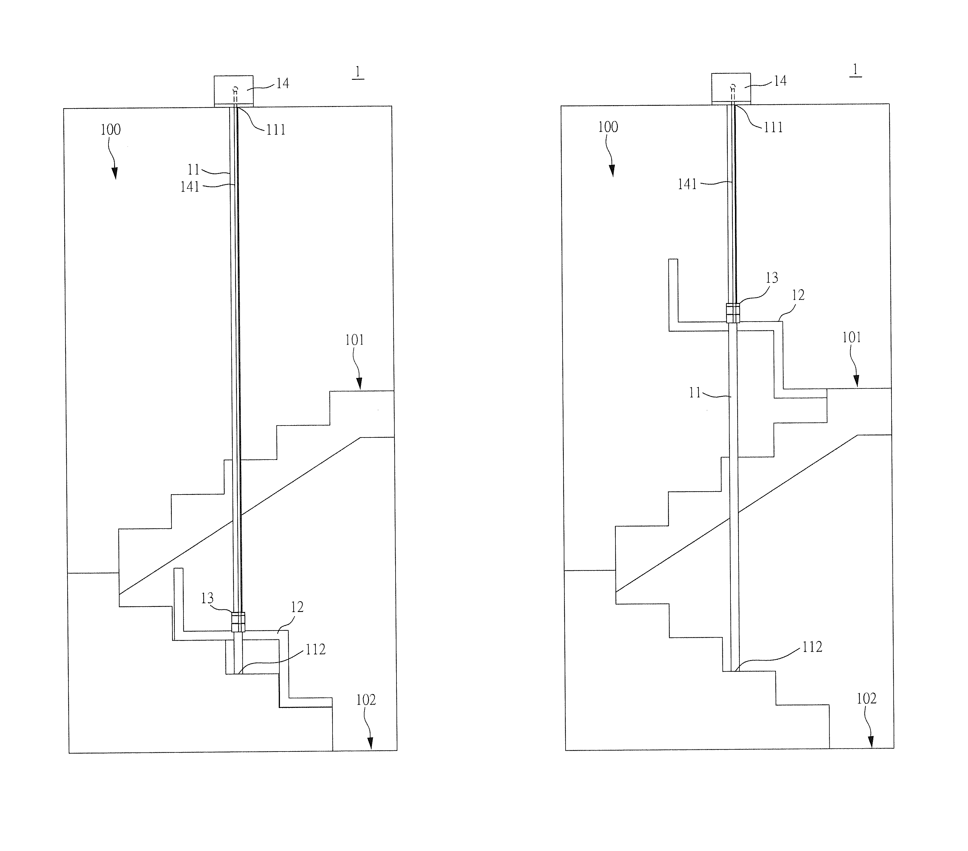
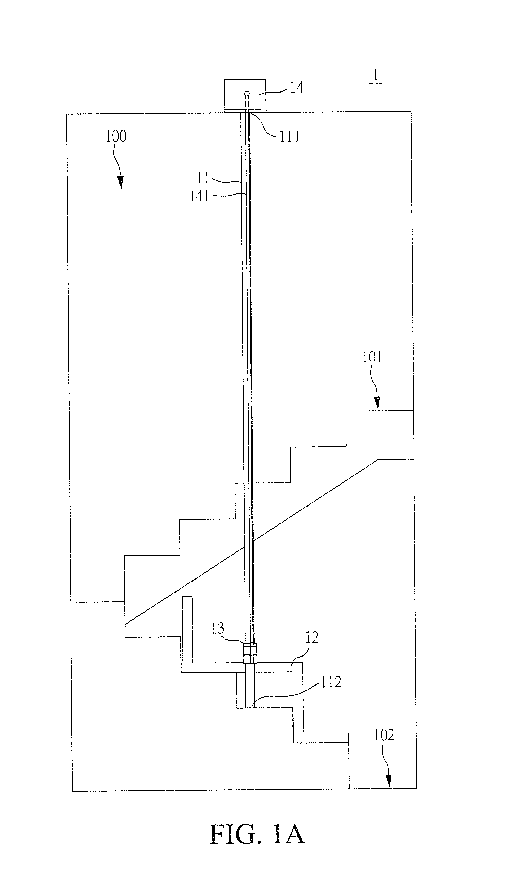
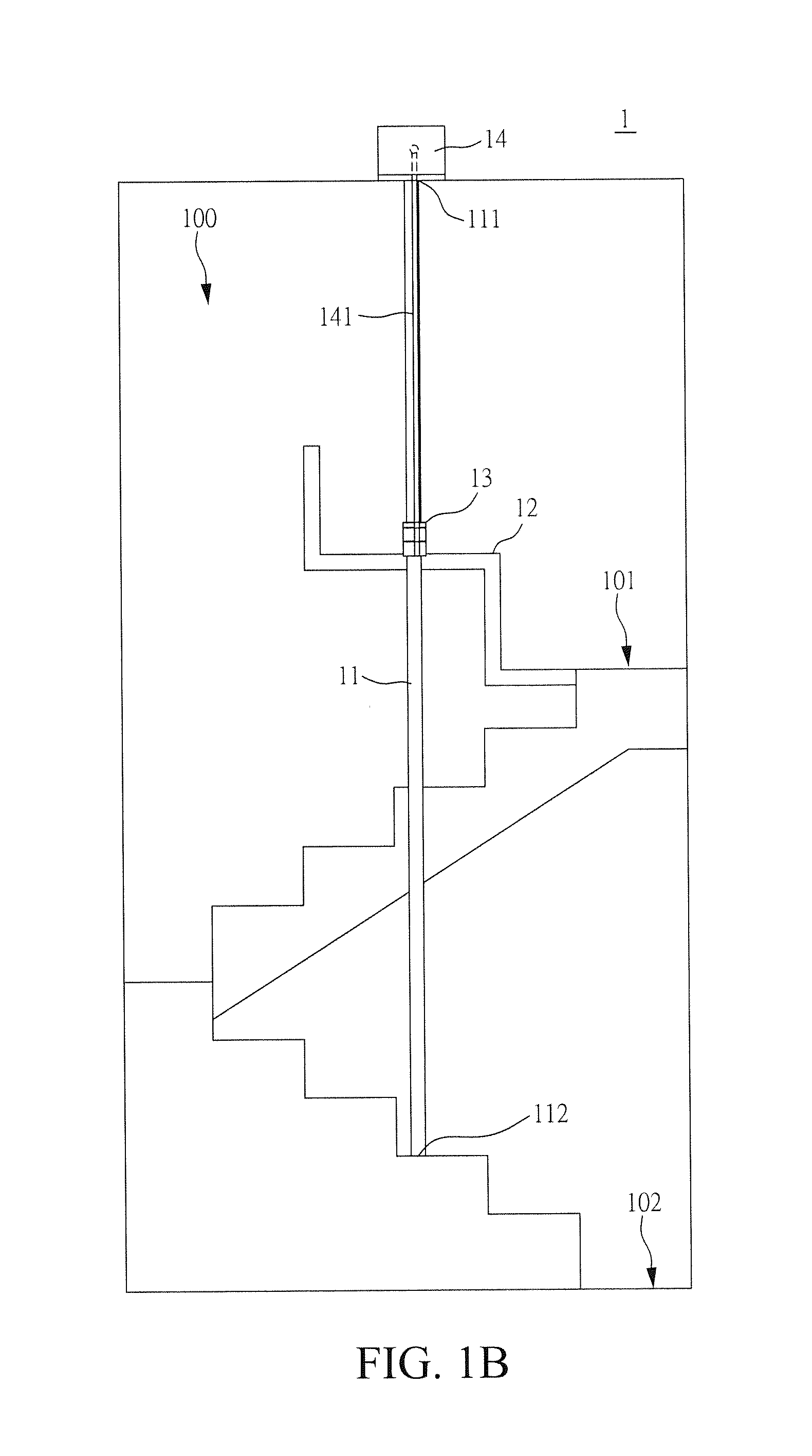
[0015]FIG. 2 shows a perspective view of a first embodiment according to the present invention. Referring to FIG. 2, in the instant embodiment, the stairwell lift 1 comprises two supporting columns 11, a passenger space 12, two sliding portions 13, and a driving mechanism 14. The supporting columns 11 can be round steel columns or angle steel columns and each supporting column 11 has a column top portion 111 and a column bottom portion 112 so that a vertical or slop rail is formed between the column top portion 111 and the column bottom portion 112 for the passenger space 12. The passenger space 12 is arranged between the two vertical columns 11. The passenger space 12 comprises a seat section 121 and a foot board 122, wherein the foot board 122 is connected to the main body 121. The sliding portions 13 are respectively mounted to two opposite sides of the seat section 121 and are respectively fit over the supporting columns 11. The sliding portions 13 may comprise rolling bearings ...

second embodiment

[0018]FIGS. 4 and 5 are perspective views illustrating a second embodiment in accordance with the present invention. Referring to FIGS. 4 and 5, in the instant embodiment, the stairwell lift 2 comprises two supporting columns 21, a passenger space 22, two sliding portions 23, and a driving mechanism 24. In the instant embodiment, in addition to a seat section 221 and a foot board 222, the passenger space 22 further comprises two front posts 223, two rear posts 224, a top board 225, a door panel 226, a back board 227, at least two arresters 228, and a control module 229. The front posts 223 and the rear posts 224 are respectively set in a circumference of the seat section 221. The top board 225 is mounted atop the front posts 223 and the rear posts 224. The driving mechanism 24 is connected, via at least one guide cable 241, to the top board 225 for driving the passenger space 22 to move along the supporting column 21 to ascend to the upstairs or descend to the downstairs (not shown)...


PUM


Abstract

A stairwell lift installed in or nearby a stairwell connecting in between upstairs and downstairs includes at least two supporting columns, a passenger space, at least two sliding portions, and at least one driving mechanism. Each supporting column has a column top portion and a column bottom portion, wherein the two column bottom portions are oppositely disposed on a space in or nearby the stairwell. The passenger space is disposed between the two supporting columns. Each sliding portion is respectively fixed on a side of the passenger space and encased each supporting column. The driving mechanism is disposed above the top of two supporting columns for driving the passenger space along the supporting columns up to the upstairs or down to the downstairs.

Description

FIELD OF THE INVENTION[0001]The present invention is a lift, specially designed to be installed in a stairwell or nearby space.BACKGROUND OF THE INVENTION[0002]With the progress of medical science and technology, the life expectancy of the modern people is being increased year by year. Most of the major countries are becoming an ageing population society. For the elderly living in residences of designs having upper and lower floors, a stairway is necessary for them to do daily activities. This causes certain troubles to the elderly or the disabled people.[0003]Various small-sized lifts are available at present for being installed inside a residence. Among these lifts, one is a household lift of which the installation requires a lift shaft. Another one is a stairway lift that comprises a rail that is arranged to follow the spiral of a stairway and is mounted to a wall of a stairway. The lift that requires a lift shaft often occupies an excessive amount of space and the installation m...

Claims


Application Information

Patent Timeline
IPC IPC(8): B66B9/00B66B11/04B66B11/02B66B1/24
CPCB66B9/00B66B11/0226B66B11/04B66B1/24B66B9/08B66B9/0853
Inventor LIN, CHEN-HSIN
Owner LIN CHEN HSIN
Why Eureka
Try Eureka