Systems and methods for forming and maintaining a high performance frc

a high-performance, frc technology, applied in nuclear reactors, greenhouse gas reduction, nuclear engineering, etc., can solve the problems of dramatic fast particle loss via collisionless stochastic diffusion, need to use external multipoles to control rotational instabilities, etc., to facilitate formation and maintenance, improve the confinement of particles, energy and flux, and stability control without negative side effects

Active Publication Date: 2015-07-02
RGT UNIV OF CALIFORNIA
View PDF21 Cites 41 Cited by
  • Summary
  • Abstract
  • Description
  • Claims
  • Application Information

AI Technical Summary

Benefits of technology

[0010]The present embodiments provided herein are directed to systems and methods that facilitate the formation and maintenance of new High Performance Field Reversed Configurations (FRCs). In accordance with this new High Performance FRC paradigm, the present system combines a host of novel ideas and means to dramatically improve FRC confinement of particles, energy and flux as well as provide stability control without negative side-effects.

Problems solved by technology

Another drawback of prior FRC system designs was the need to use external multipoles to control rotational instabilities such as the fast growing n=2 interchange instabilities.
While this technique is adequate for stability control of the thermal bulk plasma, it poses a severe problem for more kinetic FRCs or advanced hybrid FRCs, where a highly kinetic large orbit particle population is combined with the usual thermal plasma.
In these systems, the distortions of the axisymmetric magnetic field due to such multipole fields leads to dramatic fast particle losses via collisionless stochastic diffusion, a consequence of the loss of conservation of canonical angular momentum.

Method used


Image

  • Systems and methods for forming and maintaining a high performance frc
  • Systems and methods for forming and maintaining a high performance frc
  • Systems and methods for forming and maintaining a high performance frc

Examples


Embodiment Construction

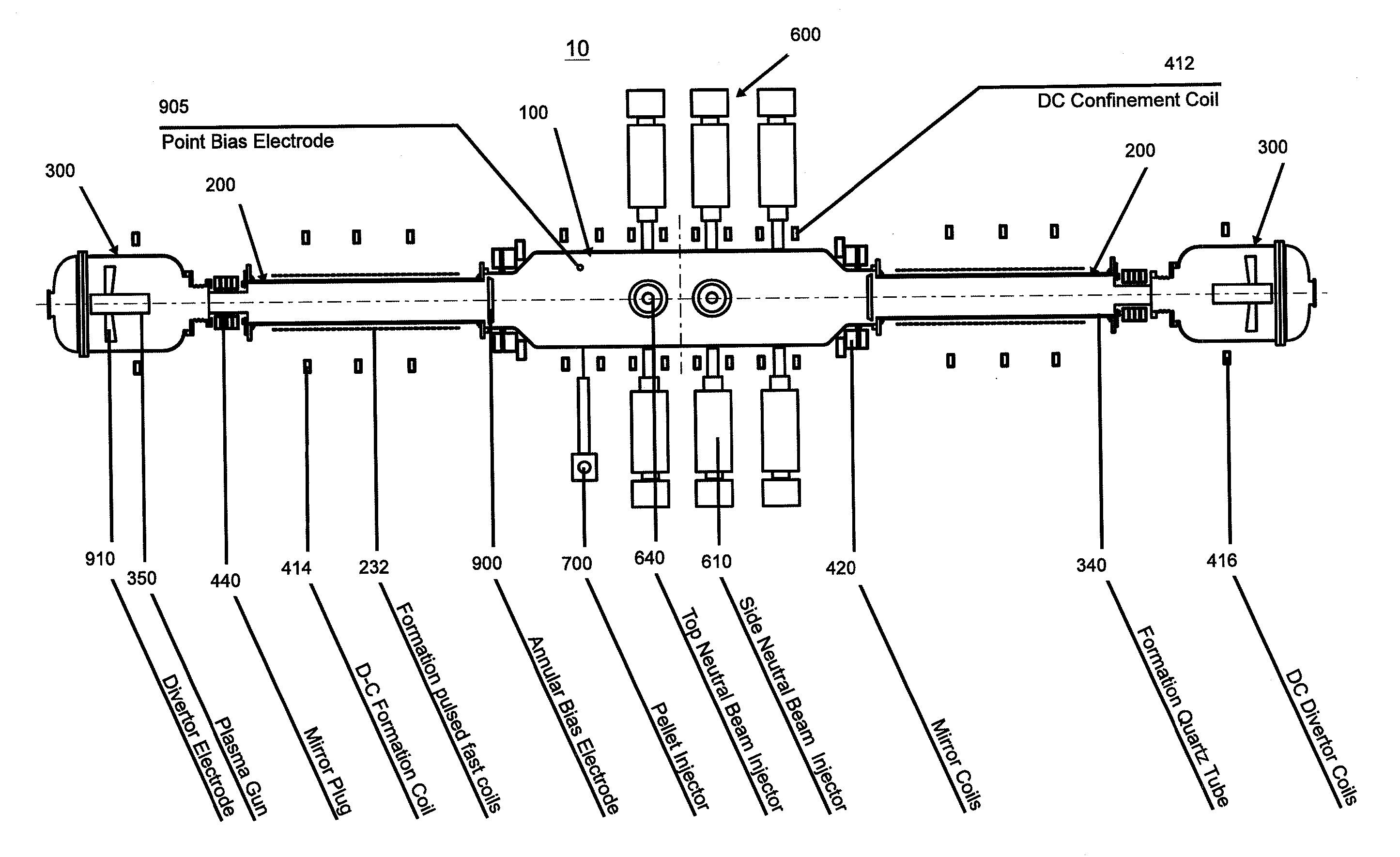
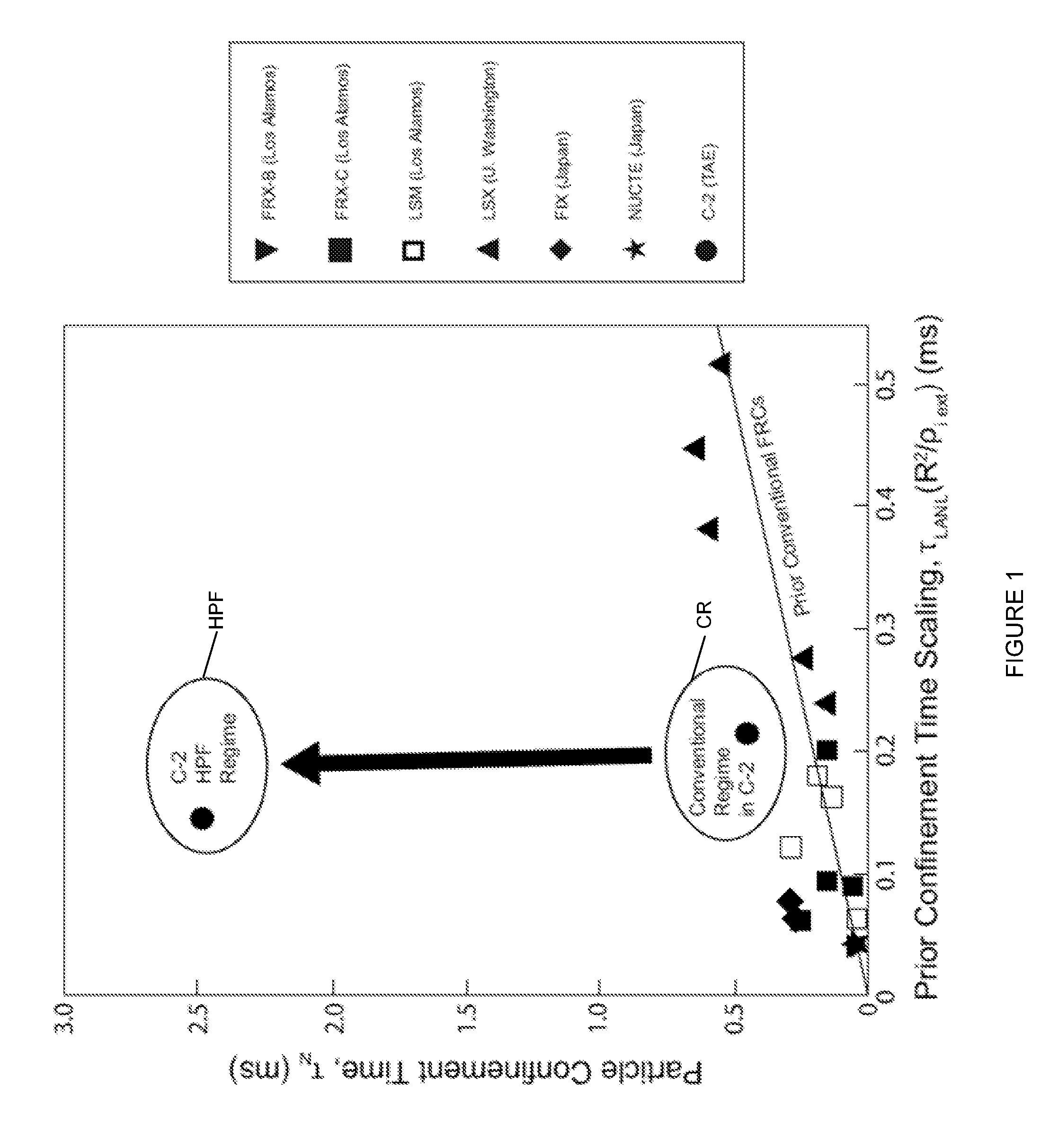
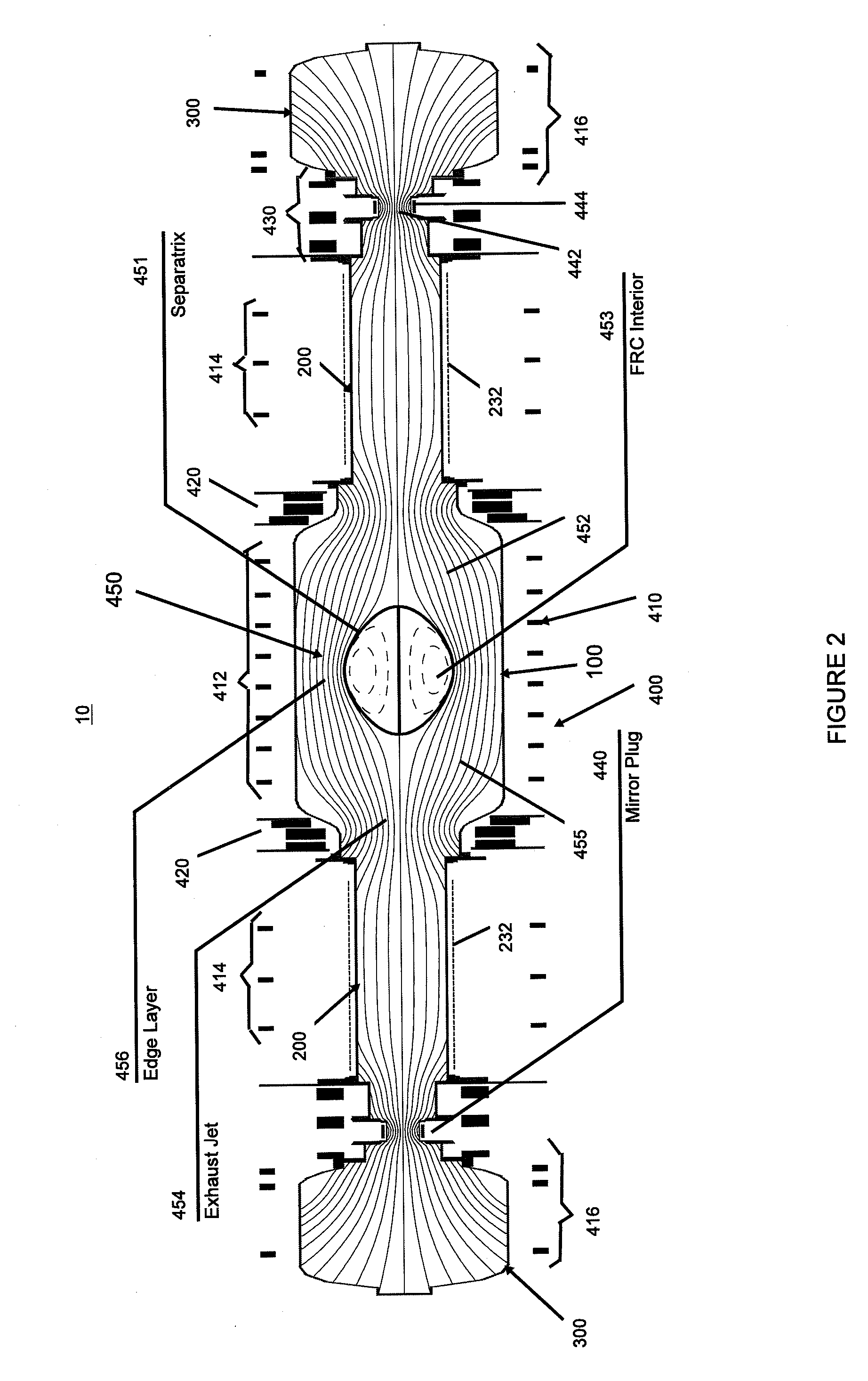
[0035]The present embodiments provided herein are directed to systems and methods that facilitate forming and maintaining High Performance Field Reversed Configurations (FRCs) with superior stability as well as superior particle, energy and flux confinement over conventional FRCs. Various ancillary systems and operating modes have been explored to assess whether there is a superior confinement regime in FRCs. These efforts have led to breakthrough discoveries and the development of a High Performance FRC paradigm described herein. In accordance with this new paradigm, the present systems and methods combine a host of novel ideas and means to dramatically improve FRC confinement as illustrated in FIG. 1 as well as provide stability control without negative side-effects. As discussed in greater detail below, FIG. 1 depicts particle confinement in an FRC system 10 described below (see FIGS. 2 and 3), operating in accordance a High Performance FRC regime (HPF) for forming and maintainin...


PUM


Abstract

Systems and methods that facilitate the formation and maintenance of new High Performance Field Reversed Configurations (FRCs). An FRC system for the High Performance FRC (HPF) includes a central confinement vessel surrounded by two diametrically opposed reversed-field-theta-pinch formation sections and, beyond the formation sections, two divertor chambers to control neutral density and impurity contamination. A magnetic system includes a series of quasi-dc coils axially positioned along the FRC system components, quasi-dc mirror coils between the confinement chamber and the adjacent formation sections, and mirror plugs between the formation sections and the divertors. The formation sections include modular pulsed power formation systems that enable FRCs to be formed in-situ and then accelerated and injected (=static formation) or formed and accelerated simultaneously (=dynamic formation). The FRC system further includes neutral atom beam injectors, a pellet injector, gettering systems, axial plasma guns and flux surface biasing electrodes.

Description

CROSS-REFERENCE TO RELATED APPLICATIONS[0001]This application claims the benefit of U.S. Provisional Application No. 61 / 559,154, filed Nov. 14, 2011, and claims the benefit of U.S. Provisional Application No. 61 / 559,721, filed Nov. 15, 2011, which applications are incorporated herein by reference.FIELD[0002]The embodiments described herein relate generally to magnetic plasma confinement systems and, more particularly, to systems and methods that facilitate forming and maintaining Field Reversed Configurations with superior stability as well as particle, energy and flux confinement.BACKGROUND INFORMATION[0003]The Field Reversed Configuration (FRC) belongs to the class of magnetic plasma confinement topologies known as compact toroids (CT). It exhibits predominantly poloidal magnetic fields and possesses zero or small self-generated toroidal fields (see M. Tuszewski, Nucl. Fusion 28, 2033 (1988)). The attractions of such a configuration are its simple geometry for ease of construction...

Claims


Application Information

Patent Timeline
Patent Type & Authority Applications(United States)
IPC IPC(8): G21B1/05G21B1/15
CPCG21B1/15G21B1/052G21B1/05H05H1/00H05H1/14Y02E30/10
Inventor TUSZEWSKI, MICHELBINDERBAUER, MICHLBARNES, DANGARATE, EUSEBIOGUO, HOUYANGPUTVINSKI, SERGEISMIRNOV, ARTEM
Owner RGT UNIV OF CALIFORNIA
Why Eureka
Try Eureka