
Device and method for anchoring soft tissue to bone

Inactive Publication Date: 2015-07-09
GROH ENTERPRISES
View PDF5 Cites 28 Cited by
  • Summary
  • Abstract
  • Description
  • Claims
  • Application Information

AI Technical Summary

Benefits of technology

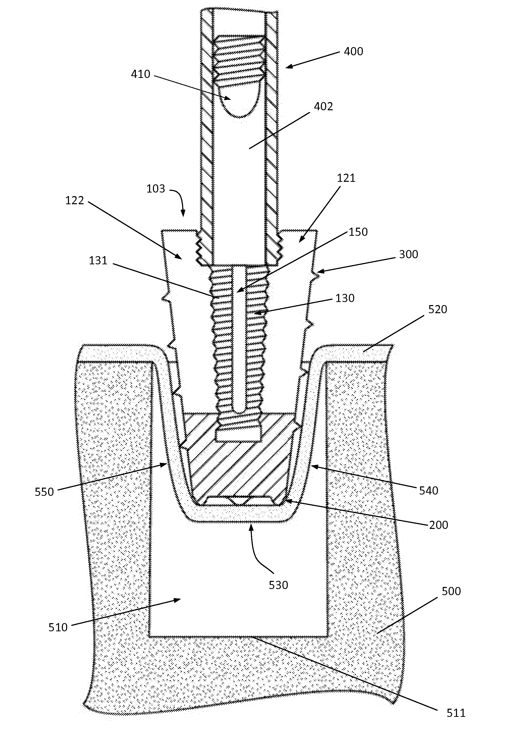
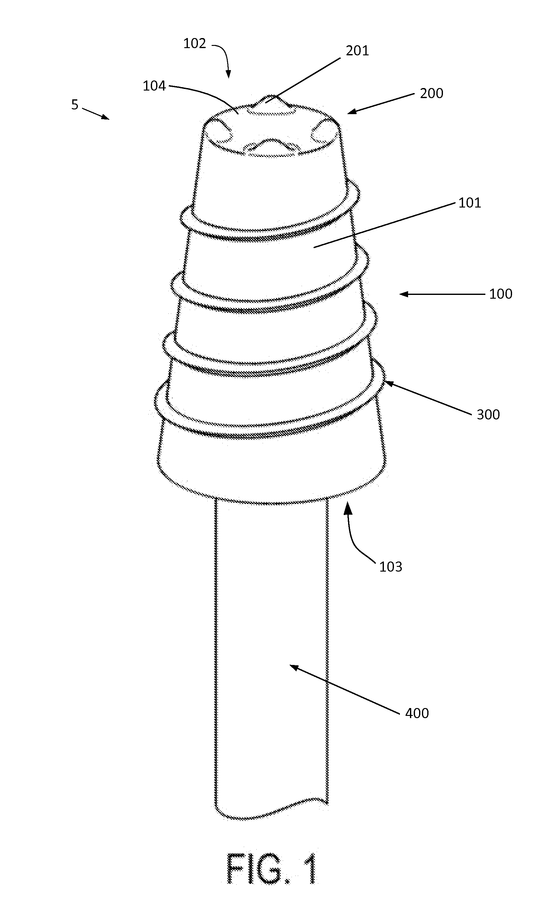
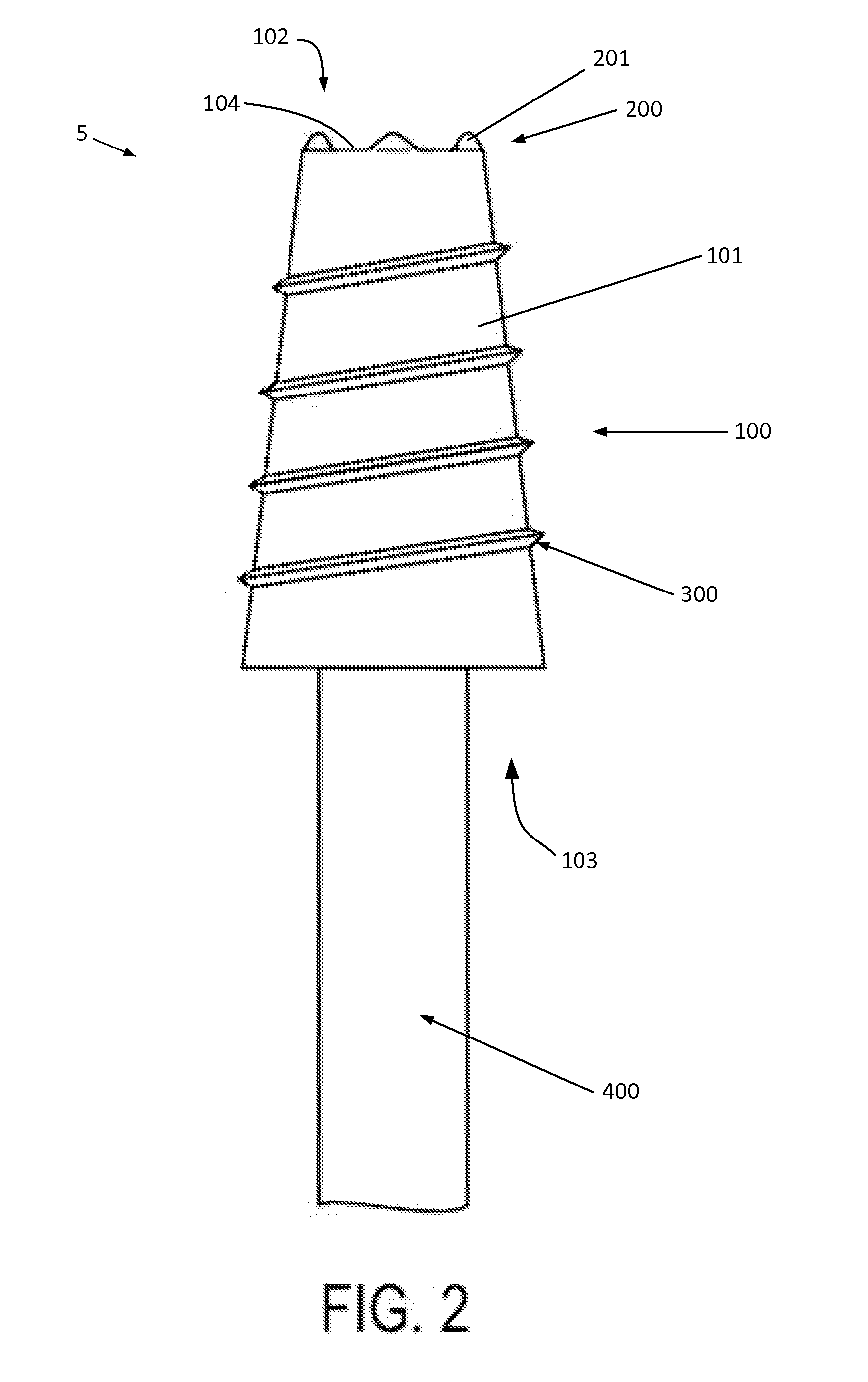
The present invention provides a surgical anchor that can securely position soft tissue within a bone cavity. The anchor has a main body with an exterior surface and a handle engagement portion. It also includes at least one anchoring member and / or feature that can securely engage soft tissue with the bottom and side surfaces of the bone cavity. The anchor can be used in various surgical procedures to securely position soft tissue. The invention also provides an expansion cavity and an insertion plug for the anchor, as well as a plurality of spaced slits that define expansion flaps. These features enhance the functionality and versatility of the surgical anchor.

Problems solved by technology

Suture anchors are designed to secure a soft tissue to a surface of the bone and may not function well for securing soft tissue to a hole that has been drilled within the bone in medical procedures such as anterior cruciate ligament reconstruction, posterior cruciate ligament reconstruction, distal bicep tendon repair, and / or the like.
Other surgical devices that exist for securing soft tissue to bone suffer from other inherent weaknesses, such as being easily removable from a hole that has been drilled within the bone, binding, twisting, and / or wrapping of the soft tissue as the surgical device is placed within the hole drilled within the bone, and / or failing to position the soft tissue into maximum contact with the hole drilled within the bone.
Additional difficulties while using those surgical devices may include the inability to fully deploy the soft tissue to the appropriate depth within the hole drilled within the bone while securely fixing the medical device to the bone.

Method used


Image

  • Device and method for anchoring soft tissue to bone
  • Device and method for anchoring soft tissue to bone
  • Device and method for anchoring soft tissue to bone

Examples


Embodiment Construction

[0036]The aspects of the invention and the various features and advantageous details thereof are explained more fully with reference to the non-limiting embodiments and examples that are described and / or illustrated in the accompanying drawings and detailed in the following description. It should be noted that the features illustrated in the drawings are not necessarily drawn to scale, and features of one embodiment may be employed with other embodiments as the skilled artisan would recognize, even if not explicitly stated herein. Descriptions of well-known components and processing techniques may be omitted so as to not unnecessarily obscure the embodiments of the invention. The examples used herein are intended merely to facilitate an understanding of ways in which the invention may be practiced and to further enable those of skill in the art to practice the embodiments of the invention. Accordingly, the examples and embodiments herein should not be construed as limiting the scope...


PUM


Abstract

A surgical anchor configured to engage soft tissue within a bone cavity defined by a bottom surface and a side surface includes a main body having an exterior surface, a proximal end, and opposing distal end; a tissue capture portion disposed proximate the distal end of the main body; a handle engagement portion disposed proximate the proximate end of the main body; and at least one anchoring member protruding from the exterior surface of the main body. The handle engagement portion is configured to operably engage an insertion handle. The tissue capture portion includes at least one tissue engaging member adapted to secure soft tissue between the anchor and the bottom surface of the bone cavity. At least a portion of the exterior surface of the main body is adapted to secure soft tissue between the anchor and the side surface of the bone cavity.

Description

CROSS-REFERENCE TO RELATED APPLICATION[0001]This application claims the benefit of U.S. Provisional Application No. 61 / 923,853, filed on Jan. 6, 2014, which is incorporated by reference in its entirety herein.BACKGROUND[0002]1. Field of the Disclosure[0003]The present disclosure relates to medical devices and procedures. More particularly, the present invention relates to devices and methods for attaching, securing, and / or otherwise fixedly connecting soft tissue to a rigid material such as bone.[0004]2. Description of Related Art[0005]Several known surgical devices are known for securing soft tissue (e.g., tendons, ligaments, and / or other soft connective tissue) to bone for various medical procedures, such as orthopedic surgery. Some of these surgical devices function alone to secure the soft tissue to bone, while others may utilize sutures in conjunction with the surgical device to secure the soft tissue to bone, such as a suture anchor.[0006]Suture anchors are designed to secure ...

Claims


Application Information

Patent Timeline
IPC IPC(8): A61B17/04A61F2/08
CPCA61B17/0401A61F2/0811A61B2017/0464A61F2002/0817A61B2017/0445A61F2002/0829A61B2017/044A61F2002/0835A61F2002/0858A61F2002/0888A61B2017/0409A61B2017/0414A61B2017/0424A61B2017/0438A61B2017/0458
Inventor GROH, GORDON I.
Owner GROH ENTERPRISES
Learn More