Shot blast cleaning wheel blade and blade and wheel combination

a technology of cleaning wheel and blade, applied in the field of shot blast equipment, can solve the problems of frequent replacement and wear of blades, and achieve the effects of reducing wear on blades and wheels, reducing safety or strength, and reducing the wear of blades and wheels

Active Publication Date: 2015-07-09
ASTECH ALLOY STEEL TECH
View PDF14 Cites 4 Cited by
  • Summary
  • Abstract
  • Description
  • Claims
  • Application Information

AI Technical Summary

Benefits of technology

[0004]The present disclosure provides improvements to shot blasting blades, including improvements that make the blades more easily removed and installed without compromising safety or strength, and others that can reduce wear on the blades and wheel. The blades disclosed herein can reduce wear on critical wheel and blade surfaces, such as the wheel surfaces proximate to blade receiving slots, and blade surfaces proximate to the same receiving slots when installed. Furthermore, the blades disclosed can be utilized with wheels having different blade receiving slot configurations.

Problems solved by technology

Because of the abrasive quality of the shot and the high speed at which the wheels and blades are turned, blades wear out and require frequent replacement.

Method used


Image

  • Shot blast cleaning wheel blade and blade and wheel combination
  • Shot blast cleaning wheel blade and blade and wheel combination
  • Shot blast cleaning wheel blade and blade and wheel combination

Examples


Embodiment Construction

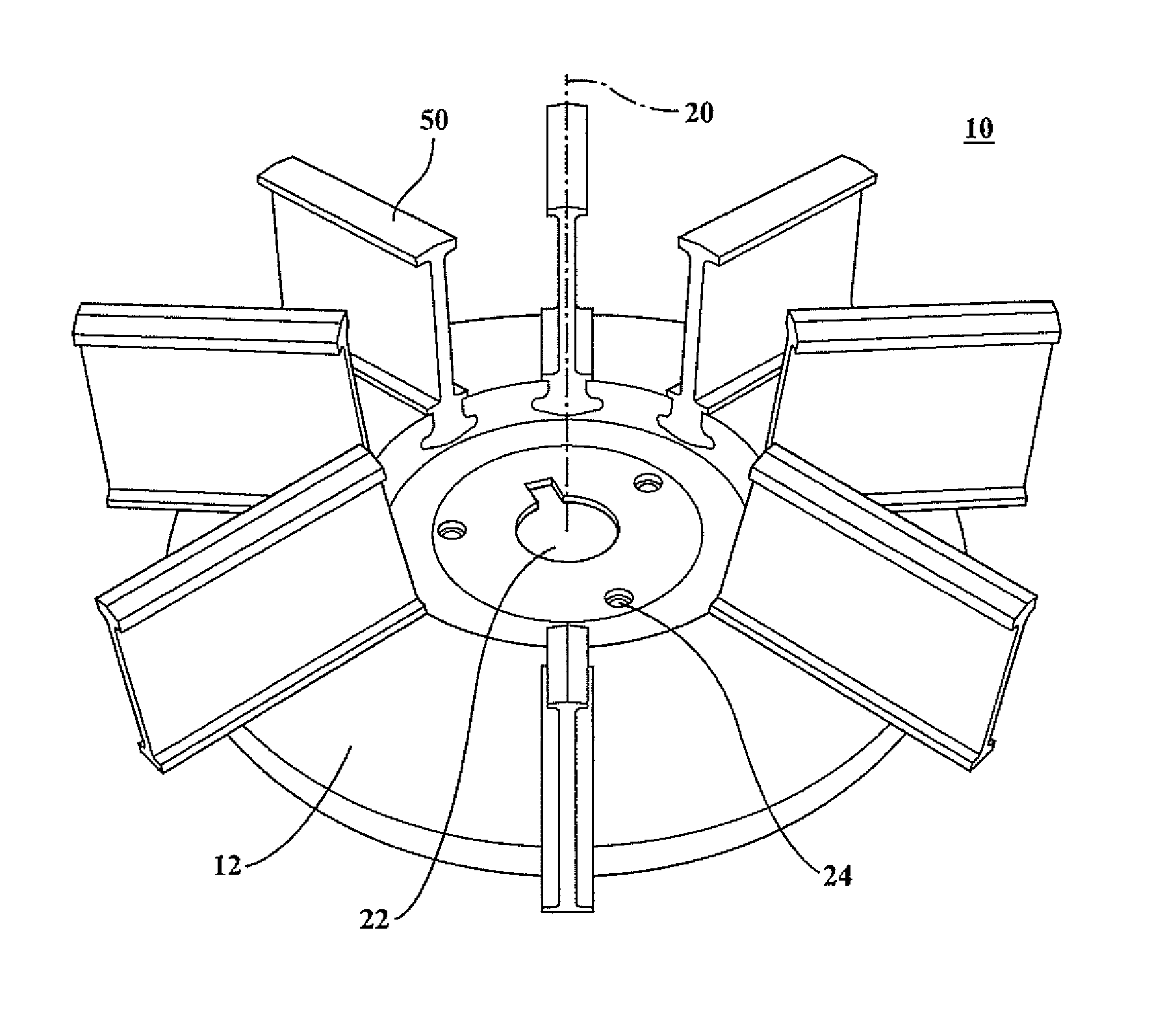
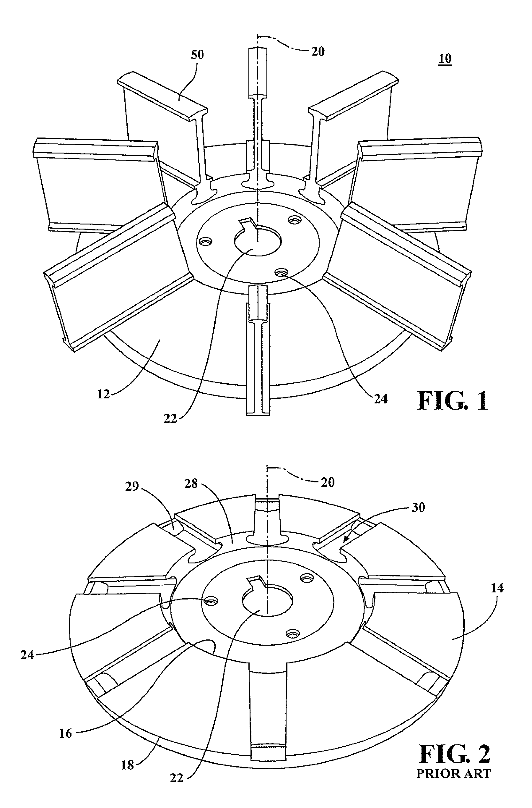
[0019]Referring first to FIG. 1, there is shown a wheel shot blasting assembly 10 comprising wheel 12 and a plurality of blades 50. The shot blasting assembly 10 is designed such that it can be rotated about center axis 20. Center axis aperture 22 can be defined in wheel 12 to receive a shaft (not shown) that is driven under power to produce the rotation of the assembly. Additional mounting apertures 24 may be included in wheel 12. It is typical for such assemblies to be rotated at approximately 2800 revolutions per minute (rpm). In one example, center axis aperture 22 can receive a shaft that is attached to a direct driven electric motor. The shot blasting assembly 10 can be incorporated within a shot blast cage (not shown) to contain and direct shot to the subject part or parts to be treated. Shot can be introduced to the blasting assembly 10 at or near the center of the wheel, and upon contact and impact with blades 50 the shot is accelerated in a radial direction towards the out...


PUM


Abstract

An improved shot blasting blade is disclosed with an attachment portion designed to slide into a radial slot in a shot blasting wheel. The blade has rails that contactingly ride on a top surface of the wheel just outside the slot, and two sets of opposed runners that extend into the slot and contact the top inner surface of the slot.

Description

FIELD OF THE DISCLOSURE[0001]This invention relates to shot blast equipment and more particularly to shot blast wheels with removable blades radially disposed thereon.BACKGROUND OF THE DISCLOSURE[0002]Shot blasting is a common technique to change surface characteristics of a variety of different parts. A shot blasting wheel can propel shot or small spheres of hard material to impact and smooth a rough surface, roughen a smooth surface, shape a surface, or remove surface contaminants. Shot blasting can be achieved by a wheel and blade assembly accelerating shot to a relatively high velocity towards the material surface of an object or group of objects to be treated. It is typical to configure equipment such that shot material is introduced into the center of a rotating wheel having a plurality of radially disposed blades mounted thereon. The shot is accelerated by the blades attached to the spinning wheel, and can be directed toward an opening in a control cage where the shot may exi...

Claims


Application Information

Patent Timeline
Patent Type & Authority Applications(United States)
IPC IPC(8): B24C5/06
CPCB24C5/06B24C5/062
Inventor BUKACH, ALAN
Owner ASTECH ALLOY STEEL TECH
Why Eureka
Try Eureka