Tent Hub Assembly

Inactive Publication Date: 2015-07-09
JIN KI HO
View PDF7 Cites 2 Cited by
  • Summary
  • Abstract
  • Description
  • Claims
  • Application Information

AI Technical Summary

Benefits of technology

[0014]The present invention is intended to overcome at least the above-described disadvantages. More specifically, the objects and advantages of the present invention are to provide a foldable instant tent that: includes a safeguard against unwanted collapse of the tent while in an open state unwanted opening of the tent while in a folded

Problems solved by technology

However, external locking mechanisms are problematic for a number of reasons such as added bulk and weight, the tendency to malfunction due to the number of interacting components, and the extra time it takes to open and fold the tent.
Even though the more recently developed hub assembly is more advantageous than the previous hub assembly having an external locking mechanism, there are several problems associated with such a configuration.
Therefore, when the inward tension from the tent fabric is weakened or when the upper tent poles do not fully engage the engaging surface, for example by strong wind exerted on the tent or by human contact, the tent is susceptible to collapsing because an additional safeguard for maintaining the tent in the open state is not present.
Another disadvantage of the foldable tent of the prior art described above is that the tent fabric is susceptible to damage when folded.
The friction caused between the hub assembly and the tent fabric could damage the tent fabric.
The

Method used


Image

  • Tent Hub Assembly
  • Tent Hub Assembly
  • Tent Hub Assembly

Examples


Embodiment Construction

[0036]Certain terminology is used in the following description for convenience only and is not limiting. The article “a” is intended to include one or more items, and where only one item is intended the term “one” or similar language is used. Additionally, to assist in the description of the present invention, words such as top, bottom, upper, lower, front, rear, inner, outer, right and left are used to describe the accompanying figures. The terminology includes the words above specifically mentioned, derivatives thereof, and words of similar import.

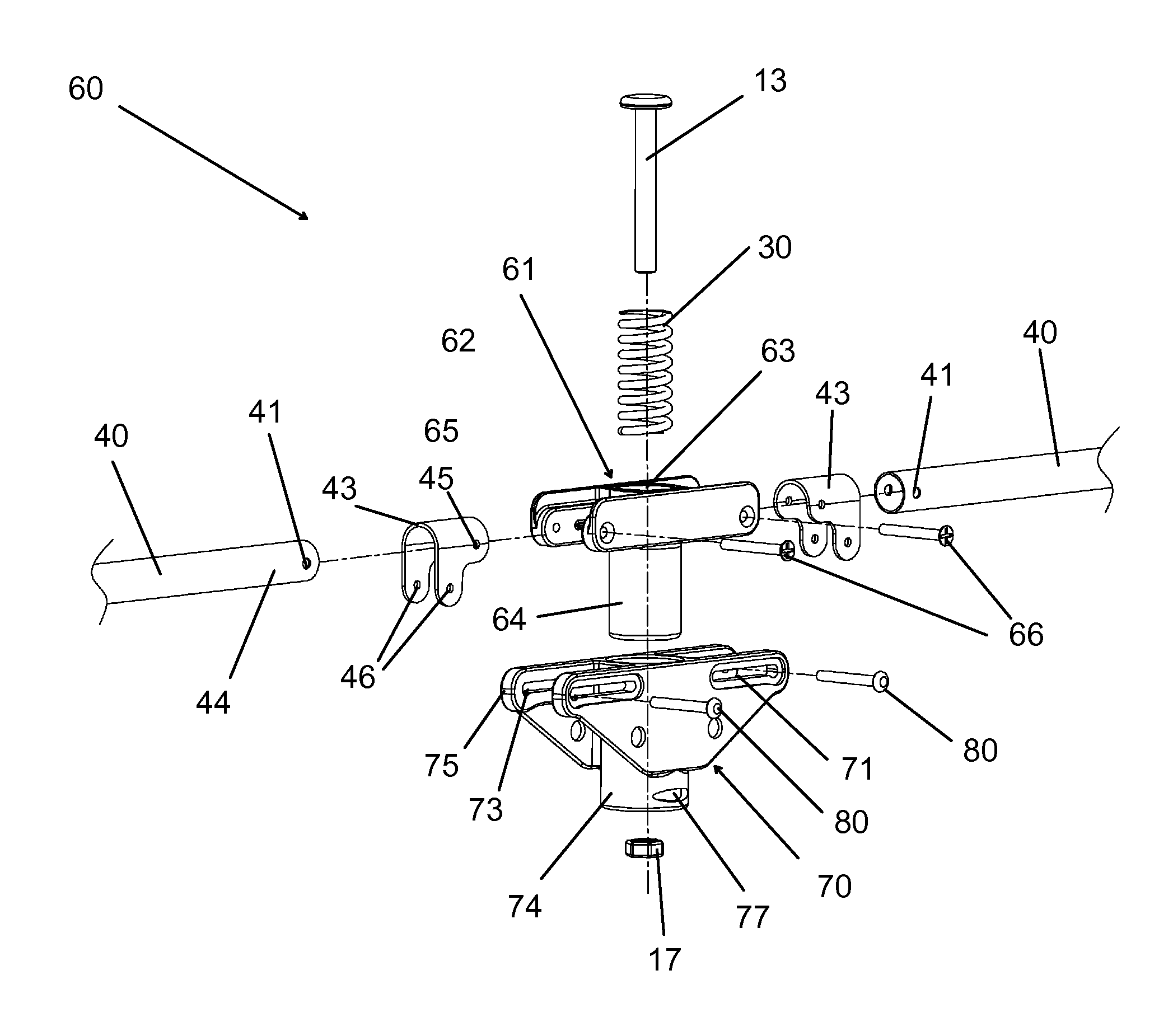
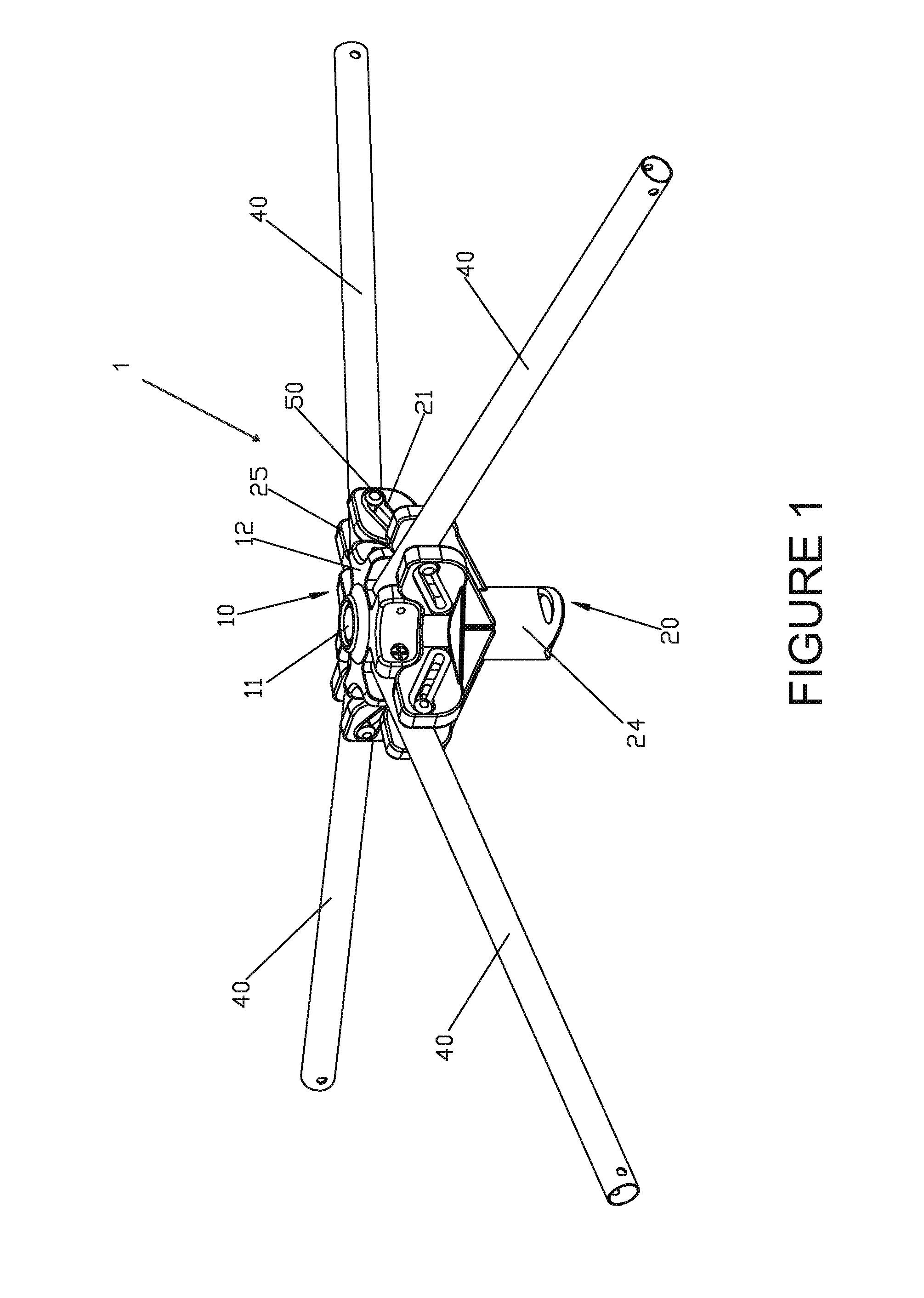
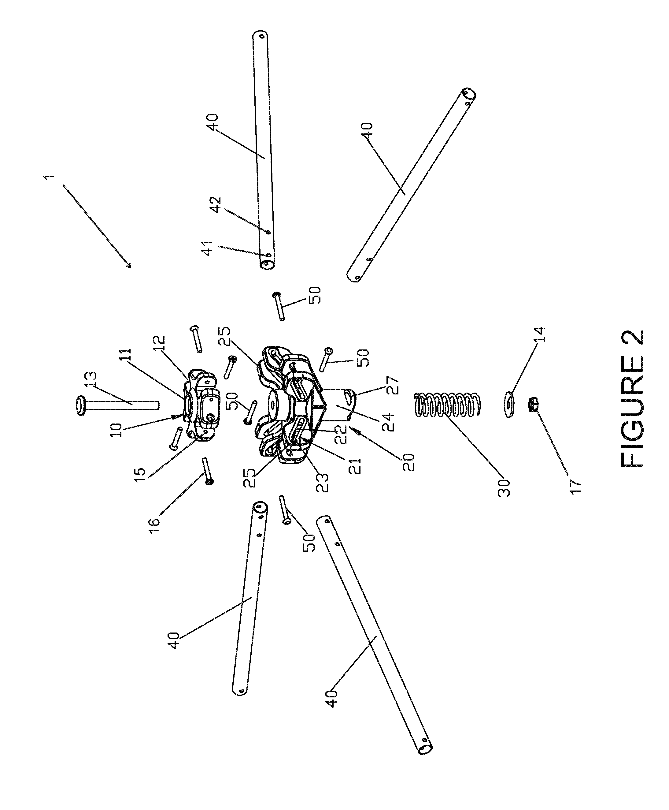
[0037]Referring to FIGS. 1-8, the hub assembly 1 is connected to the ends of a plurality of poles 40 of a tent, as shown in FIG. 8, which have the tent fabric attached to the poles 40. As shown in FIGS. 1-2, the hub assembly 1 has a body or hub 10 with a plurality of hub arms 12 radially extending from a central portion having a central aperture 11. Each hub arm 12 has a fastener aperture 15 which receives a fastener 16 that passes throu...


PUM


Abstract

A hub assembly for a tent has open, intermediate, and closed configurations, with pairs of fasteners and pins having a first distance in a first direction substantially equal to a second distance between fasteners and the pins along a second direction different from the first direction. When the first and second distances are equal, a biasing member is in a first state in both the open and closed configurations. In the intermediate configuration between the open and closed configurations, the biasing member has a second state which is compressed, and a vertical distance between pairs of fasteners and pins is greater than the first distance. Moving the poles from the intermediate configuration to either the open or the closed configurations decreases the vertical distance between the fastener and the pin which transitions the biasing member from the second state to the less compressed first state.

Description

CROSS-REFERENCE TO RELATED APPLICATIONS[0001]This application is a continuation-in-part application of U.S. application Ser. No. 14 / 251,729, filed on Apr. 14, 2014, which claims foreign priority to China Application No. 2013207091816, filed on Nov. 11, 2013, which are incorporated by reference in their entireties.BACKGROUND OF THE INVENTION[0002]1. Field of the Invention[0003]The present invention relates to a tent hub assembly, and in particular to a hub assembly which facilitates folding and unfolding of a tent.[0004]2. Description of Prior Art[0005]Foldable tents are well known in the art and have become very popular in recent years. In fact, every major retail outlet in the U.S. sells a foldable tent in one form or another. Foldable tents come in different configurations with a variety of features and manufacturers continue to improve those features. However, in general, a foldable tent comprises a tent fabric coupled to a frame assembly at a radially inner space of the frame as...

Claims


Application Information

Patent Timeline
IPC IPC(8): E04H15/48E04H15/32
CPCE04H15/32E04H15/48E04H15/42
Inventor LI, WEN XIANG
Owner JIN KI HO
Why Eureka
Try Eureka