Suspension Device

a suspension device and suspension technology, applied in the direction of safety belts, sports equipment, cleaning equipment, etc., can solve the problems of self-locking difficulty and potential safety risks for those without professional training, and achieve the effect of facilitating the deflection of the suspension device and ensuring the safety of users

Inactive Publication Date: 2015-07-23
HE SHAODUN
View PDF13 Cites 4 Cited by
  • Summary
  • Abstract
  • Description
  • Claims
  • Application Information

AI Technical Summary

Benefits of technology

[0017]The benefit of the present invention is: The suspension device as described in the present invention, provided with a control handle on one side of the suspension hole to control the deflection of the suspension device, features a self-locking function which can guarantee the safety of users. When necessary, the human body can descend by exerting pulling force on the suspension device with the control handle to force the suspension device to deflect so as to release self-locking. It is easy to operate.

Problems solved by technology

However, the disadvantage is that it finds a self-locking difficulty.
In case it needs to hover in the air for a long time, the free end of the suspend rope must be fixed; for this reason, in using the existing 8-shaped ring suspension device, there are potentially certain safety risks for those without professional training due to inconvenient operation.

Method used


Image

  • Suspension Device
  • Suspension Device
  • Suspension Device

Examples


Embodiment Construction

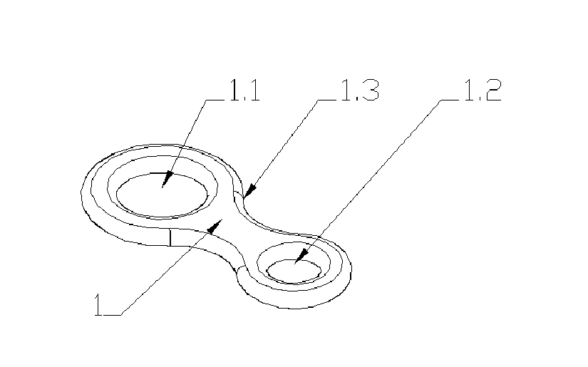
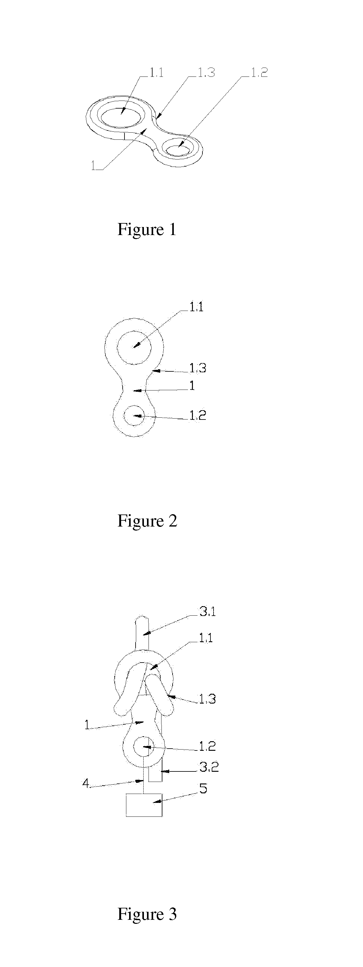
[0035]FIG. 1 to FIG. 3 are the schematic views of the existing 8-shaped ring suspension device. FIG. 1 is the structural stereogram, FIG. 2 is the structural plan and FIG. 3 is the schematic view in using.

[0036]Seen from FIG. 1 and FIG. 2, the existing 8-shaped ring suspension device mainly include suspension body 1 with rope-penetrating hole 1.1 and suspension hole 1.2.

[0037]Seen from FIG. 3 that is the schematic view in using, when used, the suspend rope passes through rope-penetrating hole 1.1 and is muff-coupled with waist 1.3 of the suspension body. Fixed end 3.1 of the suspend rope passes through rope-penetrating hole 1.1 and then is fixed on high, free end 3.2 of the suspend rope passes through rope-penetrating hole 1.1 and droops to the lower place, and human body 5 is fixed and connected with suspension hole 1.2 by fastener 4. In actual use, due to self-locking difficulty in the existing 8-shaped ring suspension device, users have to apply continuous pulling force to free e...


PUM


Abstract

The present invention provides a suspension device. A U-shaped rope-penetrating part is arranged on a suspension body; the U-shaped mouth of the U-shaped rope-penetrating part together with the suspension body form a rope-penetrating hole; a suspension hole is set in a position to one side, and a control handle which controls the deflection of the suspension device is also provided. When the human body is independently borne by the suspension hole, the fixed end and the free end of the suspend rope are pressed tightly with each other to prevent the suspend rope from sliding; the human body is suspended on the high, and the suspension device is in a self-locking state. When the human body exerts pulling force on the suspension device through the control handle, the suspension device deflect, at this time, the human body begins to descend with the rope sliding.

Description

FIELD OF THE INVENTION[0001]The present invention relates to a suspension device, in particular relates to a suspension device that descends due to body's own weight of gravity and through manual control.BACKGROUND ART[0002]The existing 8-shaped ring suspension device is characterized by a simple structure, easy to operate, so it is widely used for rock climbing, caving, working at heights, aerial rappelling etc. However, the disadvantage is that it finds a self-locking difficulty. In actual use, people have to apply continuous pulling force to the free end of the suspend rope in a bid to control the rate of descent. In case it needs to hover in the air for a long time, the free end of the suspend rope must be fixed; for this reason, in using the existing 8-shaped ring suspension device, there are potentially certain safety risks for those without professional training due to inconvenient operation.BRIEF SUMMARY OF THE INVENTION[0003]In order to overcome the self-locking difficulty ...

Claims


Application Information

Patent Timeline
Patent Type & Authority Applications(United States)
IPC IPC(8): A62B1/14
CPCA62B1/14
Inventor HE, SHAODUN
Owner HE SHAODUN
Why Eureka
Try Eureka