
Fishing reel having drag assembly

a technology of assembly and reel, which is applied in the direction of reels, applications, fishing, etc., can solve the problems of reduced productivity, difficult to form uneven surfaces, complex auxiliary washers, etc., and achieves the effects of improving production cost competitiveness, high stiffness, and enhancing productivity

Active Publication Date: 2015-07-30
DOYO ENG
View PDF13 Cites 4 Cited by
  • Summary
  • Abstract
  • Description
  • Claims
  • Application Information

AI Technical Summary

Benefits of technology

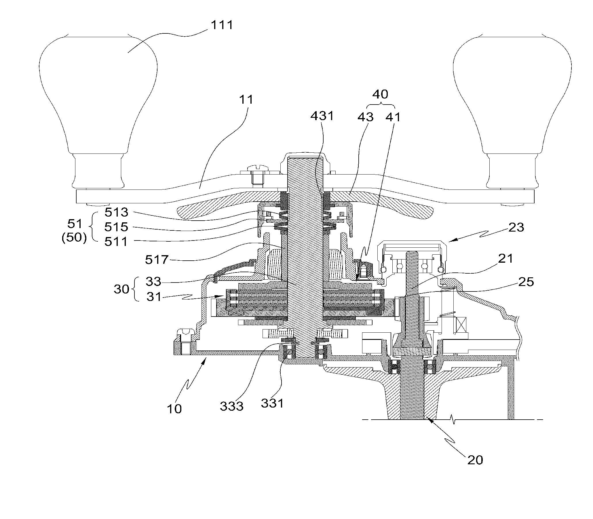
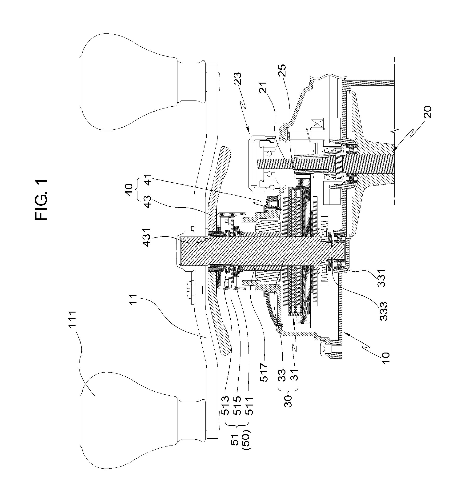
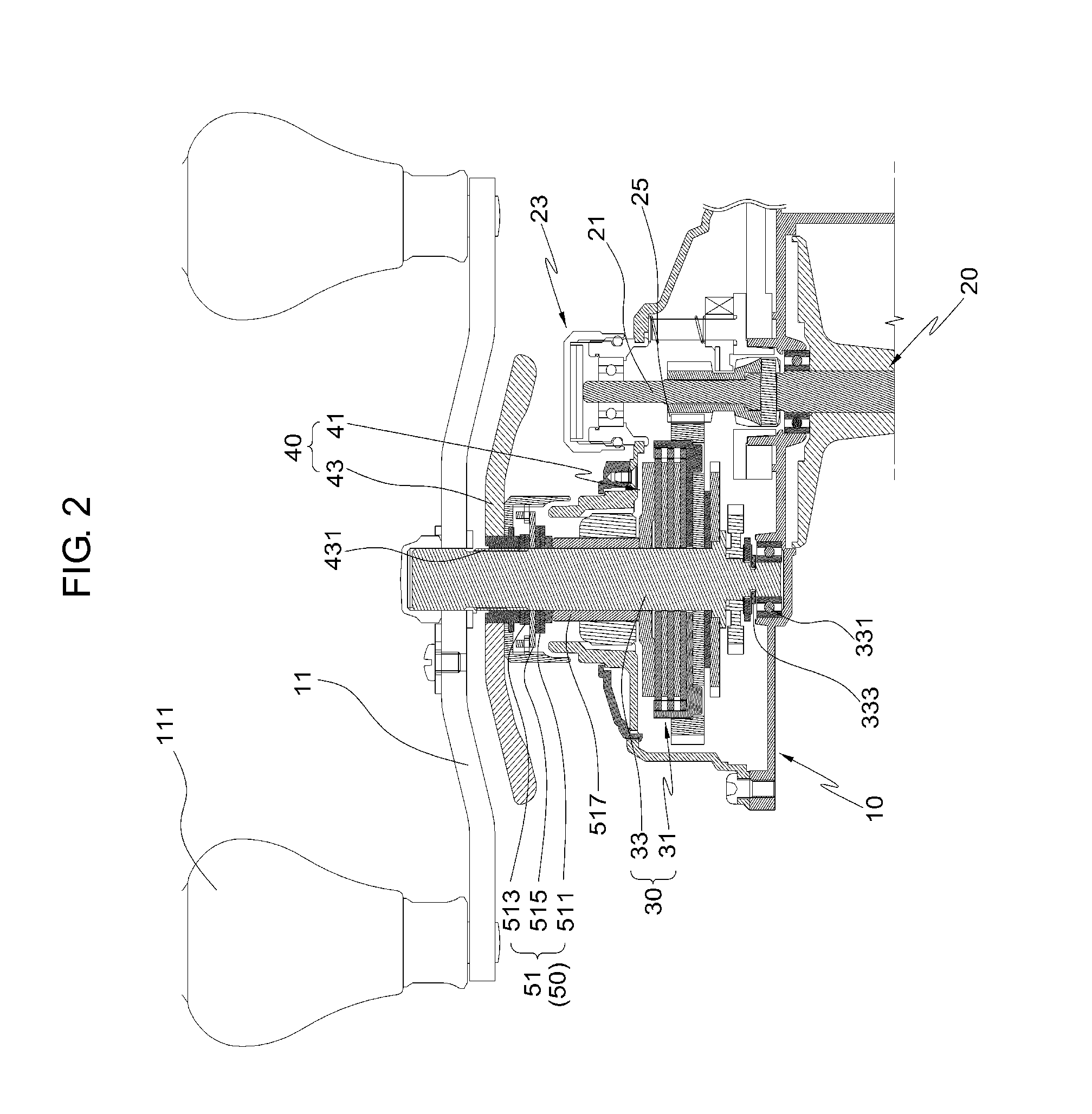
The present invention is a fishing reel with a drive unit and a drag assembly. The drag assembly prevents the fishing line from being reeled out too quickly. Unlike previous designs, the drive gear does not have any uneven surface structures that would require machining. This improves productivity and reduces production costs, while still ensuring effective braking of the spool.

Problems solved by technology

However, a process of forming the drive gear to have a shape corresponding to that of the auxiliary washer for preventing relative rotation of the drive gear and the auxiliary washer is very complex and difficult to embody.
Given this, it is very difficult to form an uneven surface corresponding to the uneven surface shape of the drag washer on the inner circumferential surface of the drive gear.
Therefore, there are problems in that the productivity is reduced, and the production cost is increased.

Method used


Image

  • Fishing reel having drag assembly
  • Fishing reel having drag assembly
  • Fishing reel having drag assembly

Examples


first embodiment

[0086]First, FIG. 3 illustrates the fastening means 315. One or more fastening holes 315a are formed in the drive gear 31. One or more fastening protrusions 315b corresponding to the respective fastening holes 315a are provided under a lower surface of the washer retainer 411. Thus, when the washer retainer 411 is received into the drive gear 31, the fastening protrusions 315b are inserted into the respective fastening holes 315a, thus preventing the washer retainer 411 from rotating relative to the drive gear 31.

second embodiment

[0087]FIG. 3 illustrates the fastening means 315. The washer retainer 411 including the sidewall 411A has an annular shape.

[0088]The fastening means 315 includes a plurality of fastening screw holes 315c, a plurality of second fastening screw holes 315d, and fastening screws 315e.

[0089]The fastening screw holes 315c are formed in the lower surface of the washer retainer 411.

[0090]The second fastening screw holes 315d are formed in the drive gear 31 at positions corresponding to the first fastening screw holes 315c.

[0091]The fastening screws 315e are tightened into the first and second fastening screw holes 315c and 315d upward based on the orientation shown in FIG. 4, whereby the washer retainer 411 can be fastened to and interlocked with the drive gear 31.

third embodiment

[0092]FIG. 5 illustrates the fastening means 315.

[0093]The fastening means 315 includes a plurality of protrusions 315f that protrude outward from the sidewall 411A of the washer retainer 411, and a plurality of fastening recesses 315g that are formed in the sidewall 411A of the receiving depression 313 of the drive gear 31 at positions corresponding to the respective protrusions 315f.

[0094]Although each protrusion 315f has been illustrated as having a semicircular shape in the drawing, it may have other shapes, for example, a rectangular shape, a pentagonal shape, etc. The bounds of the present invention should not be limited by this.

[0095]When the washer retainer 411 is inserted into the drive gear 31, the respective protrusions 315f are coupled to the respective fastening recesses 315g, whereby the washer retainer 411 and the drive gear 31 can be interlocked with each other and rotated together.

[0096]To prevent the washer retainer 411 from being removed from the drive gear 31 wh...


PUM


Abstract

A fishing reel having a drag assembly. The drag assembly brakes the unwinding rotation of a spool to prevent a fishing line from being excessively rapidly unwound from the spool and thus from being snapped when the fishing line is drawn out by a hooked fish. The drag assembly includes a washer retainer coupled to a drive gear, and a washer group having a brake washer. Therefore, there is no need for the drive gear to have a shape corresponding to the washer group, whereby the manufacturing process can be facilitated, the time it takes to manufacture the fishing reel can be reduced, and the production cost can also be reduced.

Description

BACKGROUND OF THE INVENTION[0001]1. Field of the Invention[0002]The present invention generally relates to fishing reels having drag assemblies. More particularly, the present invention relates to a fishing reel having a drag assembly that brakes an unwinding rotation of a spool to prevent a fishing line from being excessively rapidly unwound from the spool and snapping when a hooked fish draws out the line. The fishing reel includes a washer retainer coupled to a drive gear, and a washer group having a brake washer, so that there is no need for the drive gear to have a shape corresponding to the washer group, whereby the manufacturing process can be facilitated, and the time it takes to manufacture the fishing reel can be reduced.[0003]2. Description of the Related Art[0004]A conventional technique of a fishing reel having a function of braking unwinding rotation of a spool was proposed in Korean Patent Registration No. 10-1193910, entitled “Fishing Reel Having Means for Generating...

Claims


Application Information

Patent Timeline
Patent Type & Authority Applications(United States)
IPC IPC(8): A01K89/033A01K89/015
CPCA01K89/015A01K89/033A01K89/053
Inventor HYUN, KANG-HO
Owner DOYO ENG
Learn More