
Piezoelectric vibration element, piezoelectric vibrator, piezoelectric oscillator, and electronic device

a piezoelectric vibration element and piezoelectric technology, applied in piezoelectric/electrostrictive/magnetostrictive devices, piezoelectric/electrostriction/magnetostriction machines, oscillators, etc., can solve the problems of deterioration, capacitance ratio , the electric characteristics of the main vibration deteriora

Active Publication Date: 2015-07-30
SEIKO EPSON CORP
View PDF11 Cites 6 Cited by
  • Summary
  • Abstract
  • Description
  • Claims
  • Application Information

AI Technical Summary

Benefits of technology

This configuration results in a piezoelectric vibration element with low CI and minimized unnecessary modes, enhancing frequency-temperature characteristics and allowing for miniaturization while maintaining performance.

Problems solved by technology

In a vibrator having a low side ratio, a contour vibration may be easily combined with its main vibration, and accordingly, the electrical characteristics of the main vibration deteriorate.
There is a problem in that the capacitance ratio γ (the ratio C0 / C1 of electrostatic capacitance C0 to the equivalent serial capacitance C1) of the piezoelectric vibration element employing the mesa structure is relatively high (deteriorates), compared to those of the piezoelectric vibration element employing the beveled structure or the convex structure.
Since this piezoelectric vibrator can trap the vibration energy under the excitation electrode, it is disclosed that the CI is low, and it is difficult for breaking of the lead electrode to occur.
Even by applying the above-described techniques to such as small-size piezoelectric vibrator, there is a problem in that the CI (crystal impedance, equivalent resistance R1) requested from the customers cannot be acquired.

Method used


Image

  • Piezoelectric vibration element, piezoelectric vibrator, piezoelectric oscillator, and electronic device
  • Piezoelectric vibration element, piezoelectric vibrator, piezoelectric oscillator, and electronic device
  • Piezoelectric vibration element, piezoelectric vibrator, piezoelectric oscillator, and electronic device

Examples


Embodiment Construction

[0069]Hereinafter, embodiments of the invention will be described with reference to the drawings. The invention is not limited to the embodiments described below at all and includes various modified examples within the scope not departing from the concept of the invention. In addition, it cannot be determined that all the configurations described in the following embodiments are essential constituent elements of the invention.

1. Piezoelectric Vibration Element

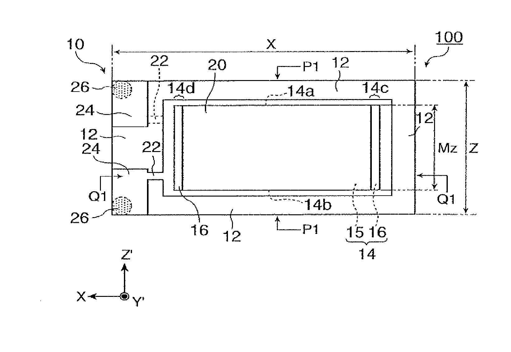
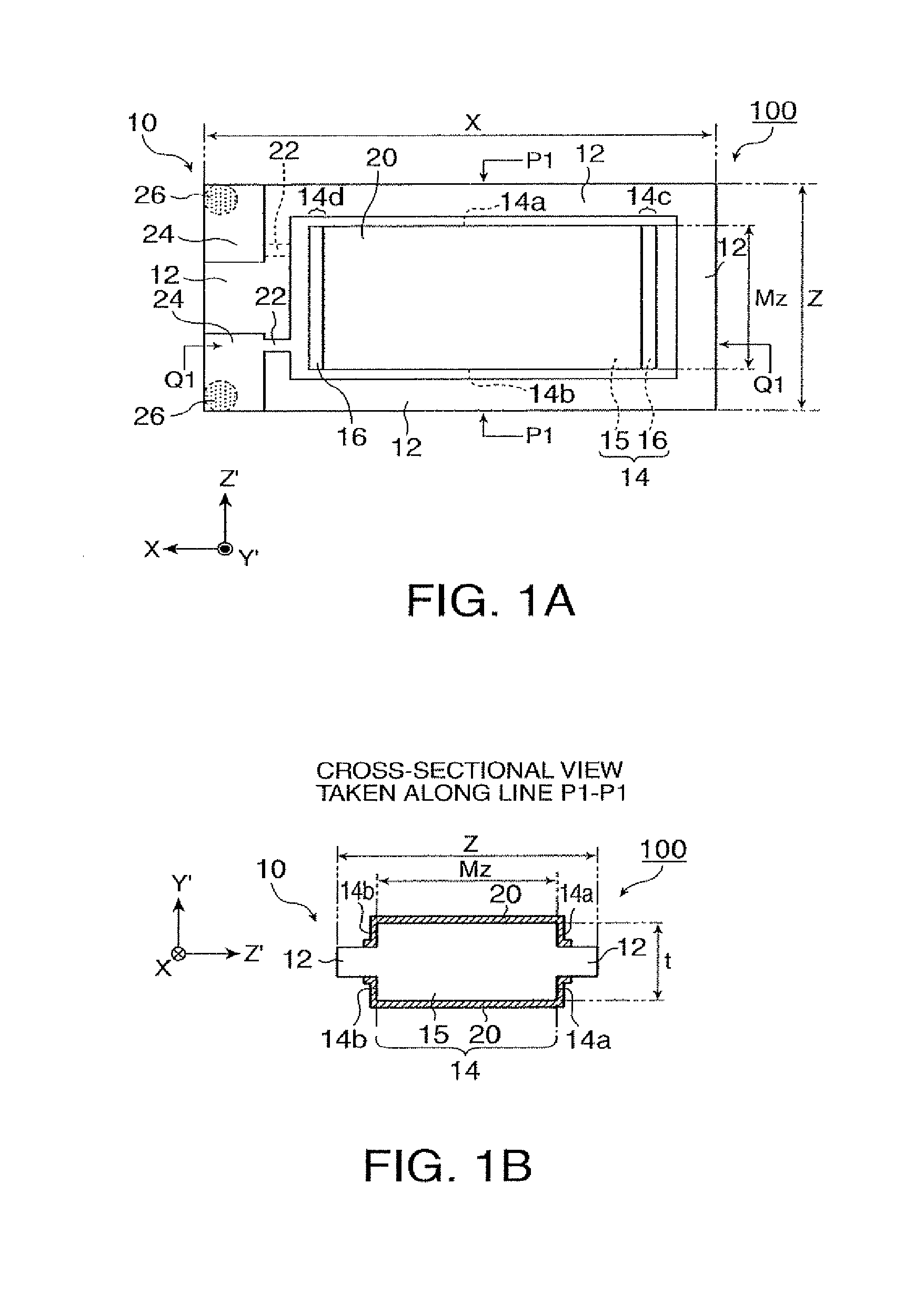
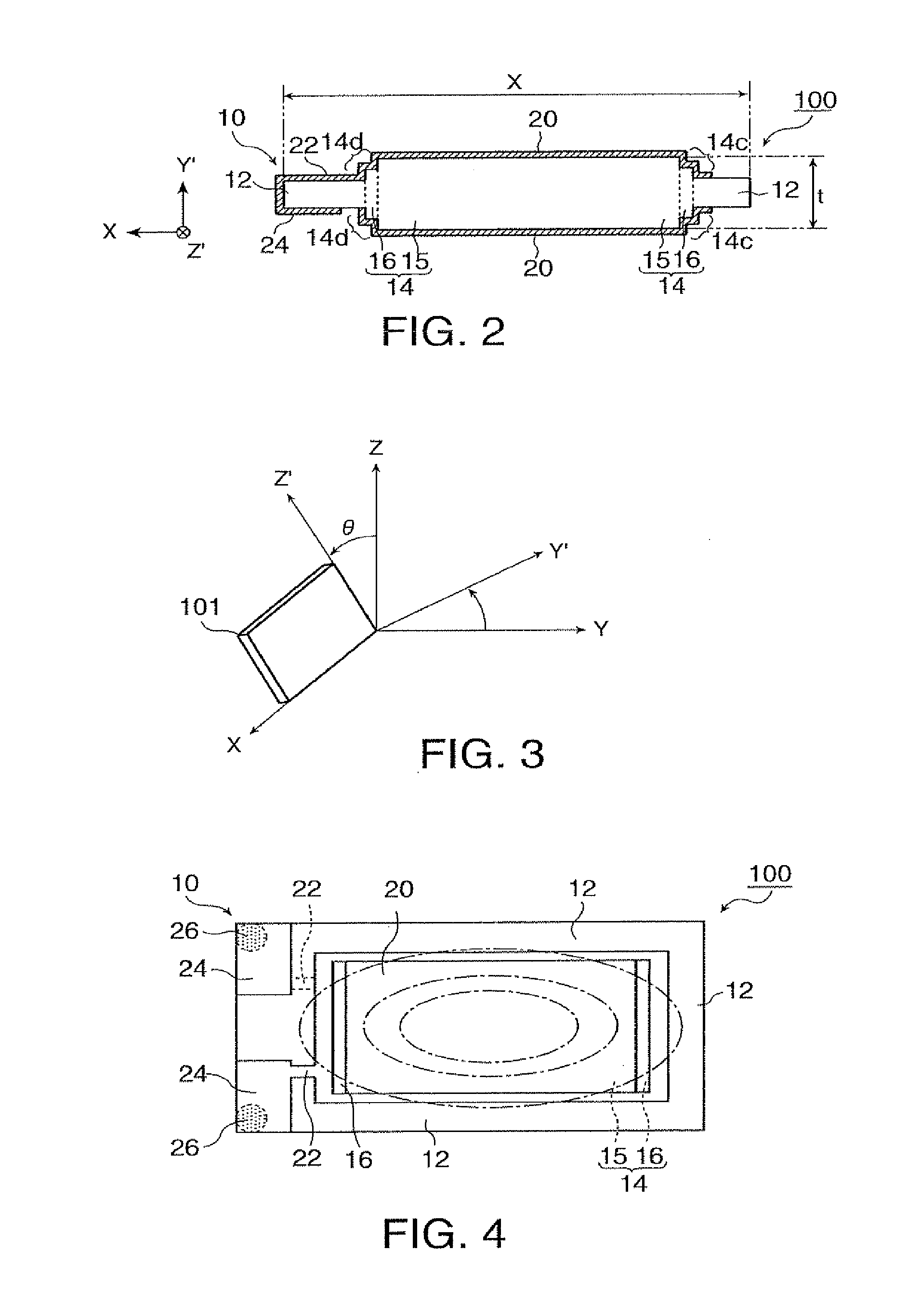
[0070]First, a piezoelectric vibration element according to this embodiment will be described with reference to the drawings. FIGS. 1A, 1B, and 2 are schematic diagrams showing the configuration of the piezoelectric vibration element 100 according to this embodiment of the invention. FIG. 1A is a plan view of the piezoelectric vibration element 100, and FIG. 1B is a cross-sectional view taken along line P1-P1 shown in FIG. 1A. FIG. 2 is a cross-sectional view taken along line Q1-Q1 shown in FIG. 1A.

[0071]The piezoelectric vibra...


PUM


Abstract

A piezoelectric vibration element includes a piezoelectric substrate including (i) an excitation portion and (ii) a peripheral portion that is integrally arranged at a periphery of the excitation portion and whose thickness is smaller than that of the excitation portion. The piezoelectric vibration element further includes excitation electrodes that are arranged in a front-and-rear relationship on front and rear principal faces of the piezoelectric substrate. The excitation portion includes a first portion that is at a location of a maximum thickness of the excitation portion and a side face that is connected to (i) a principal face of the first portion and (ii) a principal face of the peripheral portion. The side face includes level difference portions having a level difference and a face that has no level difference from the principal face of the first portion to the principal face of the peripheral portion.

Description

REFERENCE TO CO-PENDING APPLICATIONS[0001]This application is a Continuation of application Ser. No. 14 / 012,338 filed Aug. 28, 2013, which in turn is a Divisional of application Ser. No. 13 / 420,061 filed Mar. 14, 2012, now issued as U.S. Pat. No. 8,614,607, which claims priority to Japanese Patent Application JP 2011-060457 filed Mar. 18, 2011. The disclosures of the prior applications are hereby incorporated by reference herein in their entirety.BACKGROUND[0002]1. Technical Field[0003]The present invention relates to a piezoelectric vibrator of a thickness vibration mode, and more particularly, to a piezoelectric vibration element, a piezoelectric vibrator, a piezoelectric oscillator, and an electronic device having so-called a mesa structure.[0004]2. Related Art[0005]AT cut quartz crystal vibrators have a thickness-shear vibration as its vibration mode and are appropriate for miniaturization and the implementation of a high frequency, and the frequency-temperature characteristic t...

Claims


Application Information

Patent Timeline
Patent Type & Authority Applications(United States)
IPC IPC(8): H03H9/19H03B5/36H01L41/22H01L41/311H01L41/313H01L41/332
CPCH03B5/36H03H9/19H03H3/02H03H3/04H03H2003/0407H03H2003/022H03H2003/0435H03H2003/0485H03H9/177H03H9/0542H03H9/0552H03H9/1021H10N30/87
Inventor II, TOSHIHIRONAITO, MATSUTARO
Owner SEIKO EPSON CORP
Learn More