Orthosis and corrective joint

Active Publication Date: 2015-08-06
ORTEMA
View PDF2 Cites 10 Cited by
  • Summary
  • Abstract
  • Description
  • Claims
  • Application Information

AI Technical Summary

Benefits of technology

[0017]The bearing journal may particularly be provided at one end with a retention portion, on which the cam ring is releasably fixed. The retention portion may in particular be provided with a retention collar for the cam member. It is thereby readily possible to prevent the correction pad from being removed axially or falling out of the hole of the bearing member. In this embodiment, consequently, the retention portion may form a stop for an axial forward travel movement of the correction pad.
[0018]The rotor may have according to the invention a ball-bearing roller. It is thereby possible to achieve a particularly robust function of the orthe

Problems solved by technology

Although the ortheses are either available in different sizes or are also individually adapted, the joint to be treated with the orthesis often cannot be stabilized or relieved or actively corrected to the desired extent.
The ina

Method used


Image

  • Orthosis and corrective joint
  • Orthosis and corrective joint
  • Orthosis and corrective joint

Examples


Embodiment Construction

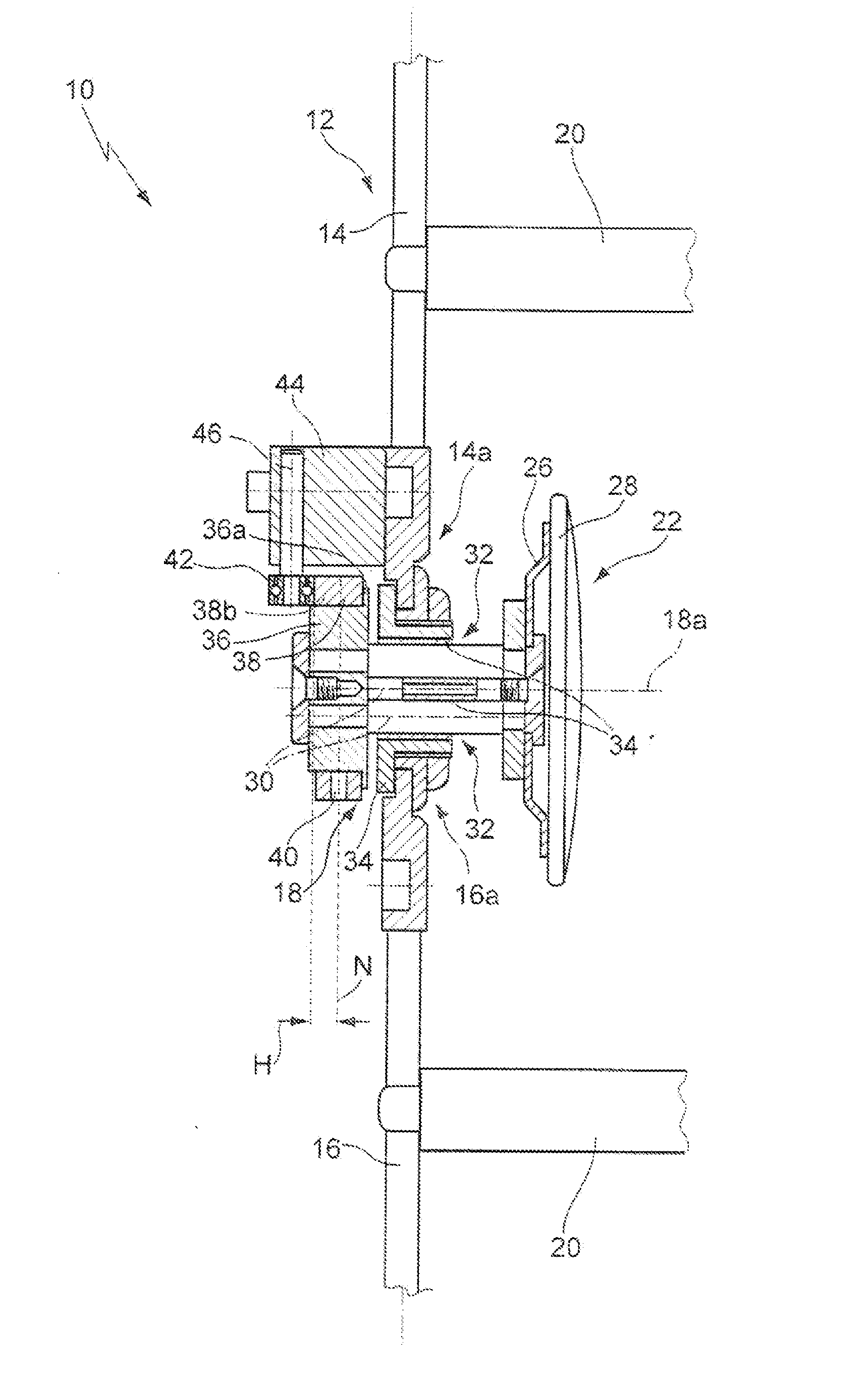
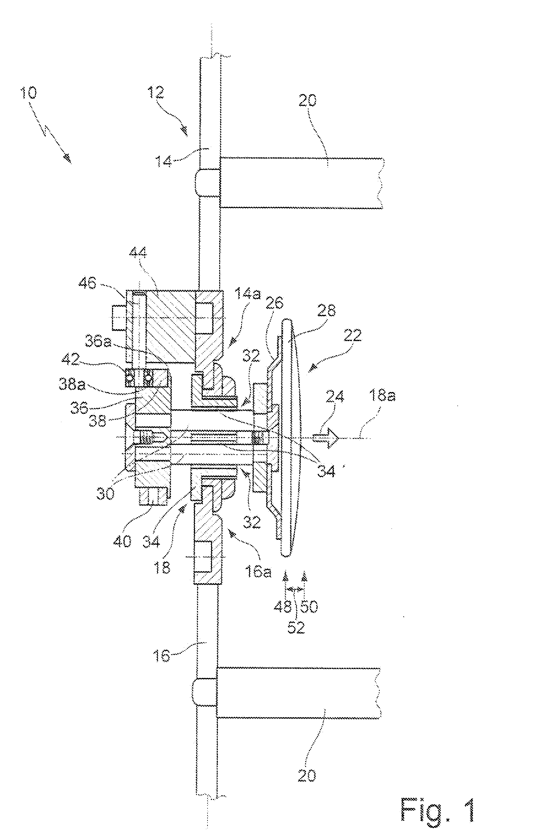
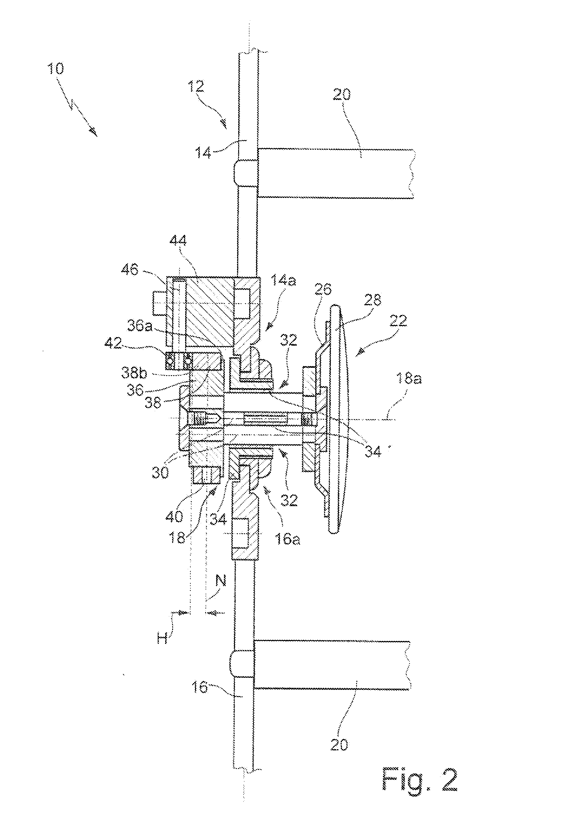
[0030]FIG. 1 is a longitudinally sectioned cut-out of an orthesis 10 according to the invention. The orthesis 10 serves to stabilize a knee joint which is not illustrated in greater detail and has a joint rail 12 having a first and a second rail portion 14, 16. The two rail portions are connected to each other by means of a correction joint 18 in the form of a rotary joint at the mutually facing ends 14a, 16a thereof. Fixing means 20 are used to fix the orthesis to the upper leg or lower leg of a person to be treated (not shown). The fixing means 20 are variably adjustable in terms of the axial position thereof on the rail portions 14, 16.

[0031]The correction joint 18 has a joint axle (axis) 18a, about which the two rail portions 12, 14 can be pivoted relative to each other. There is arranged on the joint rail 12 a correction pad 22 which can be moved by a pivoting movement of the two rail portions 12, 14 in the rotary joint 18 along the joint axle 20 in the direction towards and co...


PUM


Abstract

An orthesis for stabilizing a joint has a joint rail having a first and a second rail portion which can be pivoted relative to each other about a joint axle. The orthesis has a pressure member which can be adjusted by a relative pivoting of the two rail portions about the joint axle in the direction towards and counter to the joint to be stabilized. One of the two rail portions has a cam disc, and the other of the two rail portions has a rotor which is guided on the cam disc, wherein the cam disc or the rotor is axially fixed in position on the correction pad.

Description

CROSS-REFERENCE TO RELATED APPLICATIONS[0001]This continuation application claims priority to PCT / EP2013 / 071005 filed on Oct. 9, 2013 which has published as WO 2014 / 060251 A1 and also the German application number 10 2012 218 804.5 filed on Oct. 16, 2012, the contents of which are fully incorporated herein with these references.FIELD OF THE INVENTION[0002]The present invention relates to an orthesis for stabilizing, guiding and / or correcting a joint.BACKGROUND OF THE INVENTION[0003]Ortheses have been used for some time as an auxiliary medical means for functionally stabilizing, relieving, guiding and / or correcting joints. For instance, knee ortheses are used, for example, after treating ruptures of the anterior or posterior cruciate ligament, after collateral ligament lesions and in the case of meniscus and cartilage damage.[0004]The ortheses generally have a pair of joint rails each having a first and a second rail portion which are connected to each other in an articulated manner ...

Claims


Application Information

Patent Timeline
IPC IPC(8): A61F5/01A61F5/30
CPCA61F5/0102A61F5/30A61F5/0123A61F2005/0174
Inventor SEMSCH, HARTMUTBRUEGGEMANN, GERT-PETERKUESEL-FELDKER, MARTIN
Owner ORTEMA
Why Eureka
Try Eureka