
Retractor and operating method

a retractor and operating method technology, applied in the field of retractors and operating methods, can solve the problems of high injury risk, spring pressure pieces that cannot be cleaned and disinfected with great effort, etc., and achieve the effect of simplifying the understanding of the subject matter

Active Publication Date: 2015-08-13
KARL STORZ GMBH & CO KG
View PDF12 Cites 6 Cited by
  • Summary
  • Abstract
  • Description
  • Claims
  • Application Information

AI Technical Summary

Benefits of technology

The invention is a retractor that has a large range of travel and can be used more efficiently and quickly. The retractor has a handle with a movable actuation device that can be moved to different positions to access the retractor. The handle has a separate range of travel that is freed up to move the actuation device to different positions. This makes it easier and faster to use the retractor.

Problems solved by technology

Considerable force has to be applied here, both for coupling and also for uncoupling, since the restoring force of the spring pressure piece always has to be overcome; this poses a high risk of injury since an operator can always slip when applying pressure.
Moreover, the spring pressure piece can only be cleaned and disinfected with great effort.

Method used


Image

  • Retractor and operating method
  • Retractor and operating method
  • Retractor and operating method

Examples


Embodiment Construction

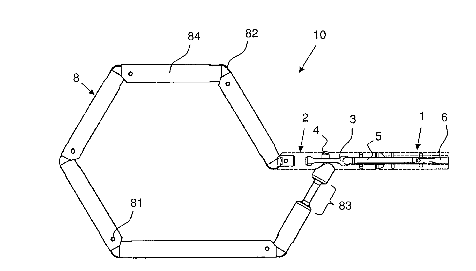
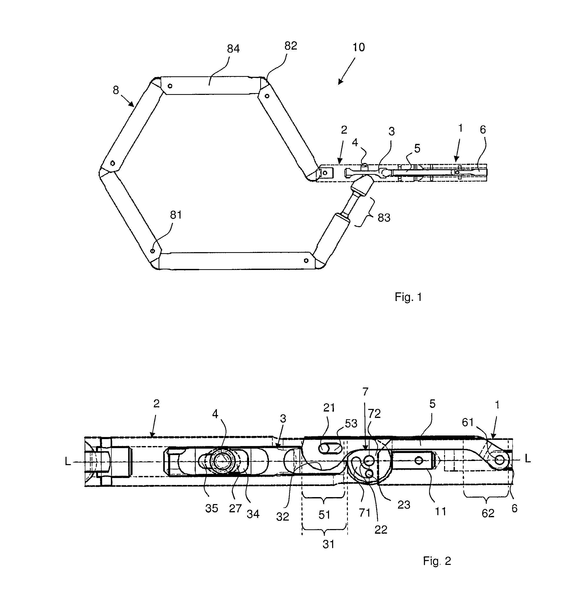
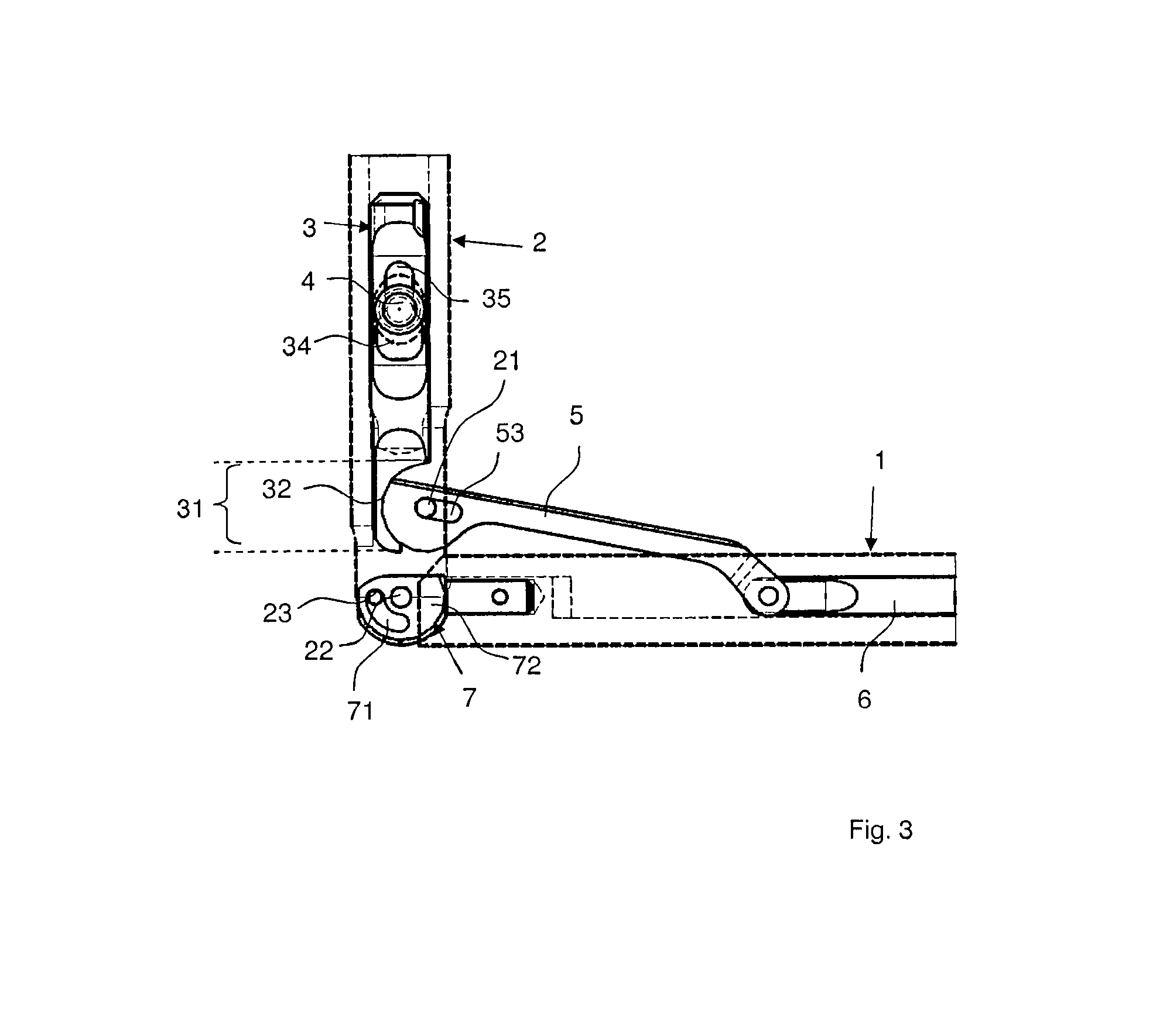
[0056]FIG. 1 shows the retractor 10 according to the invention, composed mainly of the retraction structure 8 and also of the first shaft portion 1 and second shaft portion 2. The retraction structure 8 is provided for the purpose of being placed under or around an organ, for example under the liver, in order to hold the latter away from an operating site, wherein the retraction structure 8 is in most cases positioned under an organ in order to avoid “blind” maneuvering behind the organ. The retraction structure 8 has several ring elements 84, which are connected to each other via hinges so as to be pivotable about the hinge axes. The visible fixing pin 81 is responsible for fixing the ball joint, while the hinge axle is concealed. The hinges each have a nontraumatic, rounded hinge body 82, such that no tissue parts can get caught therein. At its free end, the retraction structure 8 is connected to the distal end of the second shaft portion 2, and its other end is likewise connected...


PUM


Abstract

A retractor for endoscopic surgery, having a first shaft portion, in which an actuation device is movable, and a second shaft portion coupled pivotably thereon. A transmission arm is articulated on a distal end of the actuation device. A retraction structure is connected to a distal end of the second shaft portion, which retraction structure can be releasably coupled, with its other end, to the second shaft portion via a coupling device. The coupling device has a slide, which is guided in the second shaft portion. The transmission arm is articulated on the second shaft portion by way of a peg-and-slot connection and is operatively coupled to the slide in order to move the latter longitudinally, wherein the coupling device can be transferred to a release state by longitudinal movement of the slide. An operating method for the retractor is also disclosed.

Description

FIELD OF THE INVENTION[0001]The following invention relates to a retractor and to an operating method for the retractor.BACKGROUND OF THE INVENTION[0002]In endoscopic surgery, retractors are used to keep organs away from the operating site, so as to have a clear view and sufficient freedom of movement. The retractors usually have an actuation handle, which is coupled via a shaft to a flexible retraction structure, the latter being composed of several link elements that are interconnected in an articulated manner. For insertion into the body or for passage through a trocar, the link elements are oriented in alignment with the shaft, and it is only when inside the body that they are shaped to form a ring or hook for receiving the organ. In order to be closed to form a ring, the retraction structure has, on the last distal link element, a connecting means connected to the shaft. The ring is shaped with the aid of a second endoscopic instrument, for example gripping forceps, introduced ...

Claims


Application Information

Patent Timeline
IPC IPC(8): A61B17/02
CPCA61B17/0218
Inventor MERZ, ROBINSTEFAN, JOCHEN
Owner KARL STORZ GMBH & CO KG
Learn More