
Detection of geomagnetically-induced currents with power line-mounted devices

a technology of geomagnetically induced current and power line, which is applied in the direction of measuring devices, magnetic measurements, instruments, etc., can solve the problems of large installation effort, large volume of prior art systems for measuring gics, and inability to handle dc currents well in modern transmission systems

Active Publication Date: 2015-08-13
SMART WIRES
View PDF10 Cites 45 Cited by
  • Summary
  • Abstract
  • Description
  • Claims
  • Application Information

AI Technical Summary

Benefits of technology

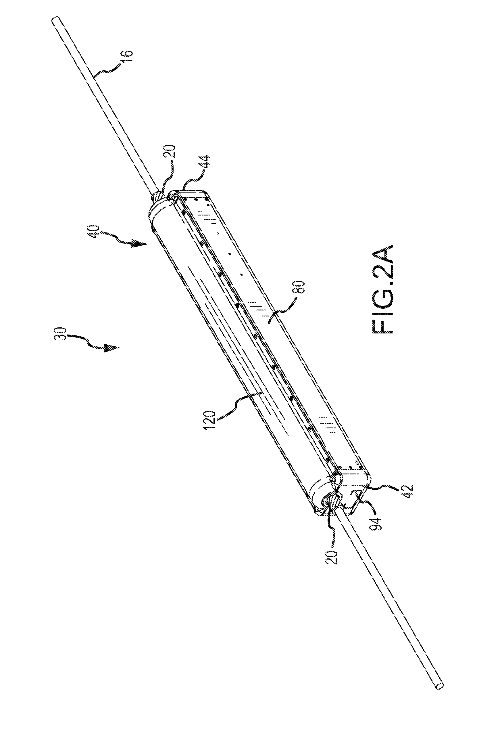
The present invention relates to a device and method for monitoring for geomagnetically-induced current (GIC) on a power line. The device, called a GIC monitor, includes a magnetic core with an air gap and a magnetic sensor positioned in the air gap. The magnetic sensor produces an output signal that is representative of the magnetic field in the air gap. The device can identify GIC by analyzing the output signal from the magnetic sensor and can also calibrate the value of the GIC. The device can be used to monitor for GIC on a power line and can be easily installed and maintained.

Problems solved by technology

A significant issue currently plaguing power transmission systems may be characterized as geomagnetically-induced currents (GICs), which are currents induced in a power line due to time-varying magnetic fields external to the Earth and resulting time-varying magnetic fields along the Earth's surface.
Unfortunately, modern transmission systems do not handle DC currents well.
For example, high DC currents may cause undesirable resistive heating of components such as transformer windings which can cause such components to fail and result in a partial failure of the power transmission system.
Prior art systems for measuring GICs can be bulky, expensive, and require major efforts to be installed.

Method used


Image

  • Detection of geomagnetically-induced currents with power line-mounted devices
  • Detection of geomagnetically-induced currents with power line-mounted devices
  • Detection of geomagnetically-induced currents with power line-mounted devices

Examples


Embodiment Construction

[0071]While the disclosure is susceptible to various modifications and alternative forms, specific embodiments thereof have been shown by way of example in the drawings and are herein described in detail. It should be understood, however, that it is not intended to limit the disclosure to the particular form disclosed, but rather, the disclosure is to cover all modifications, equivalents, and alternatives falling within the scope as defined by the claims.

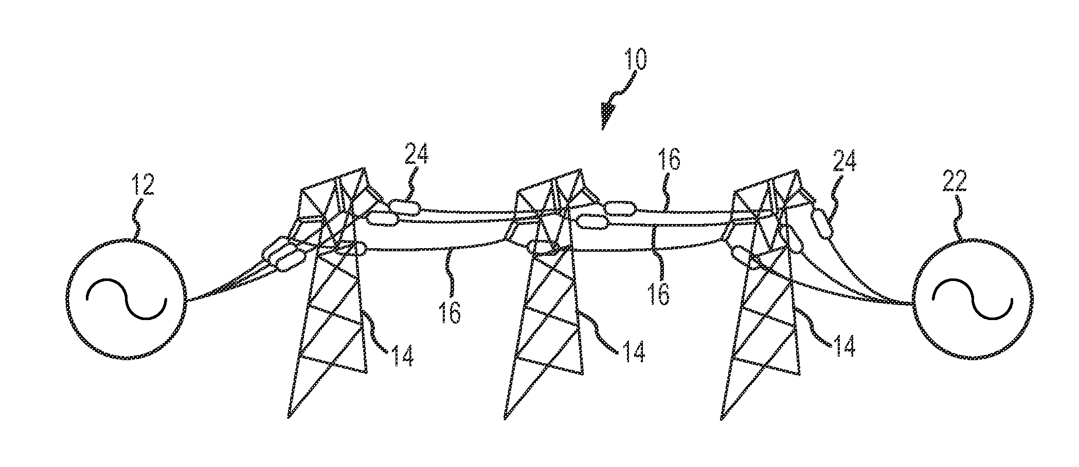
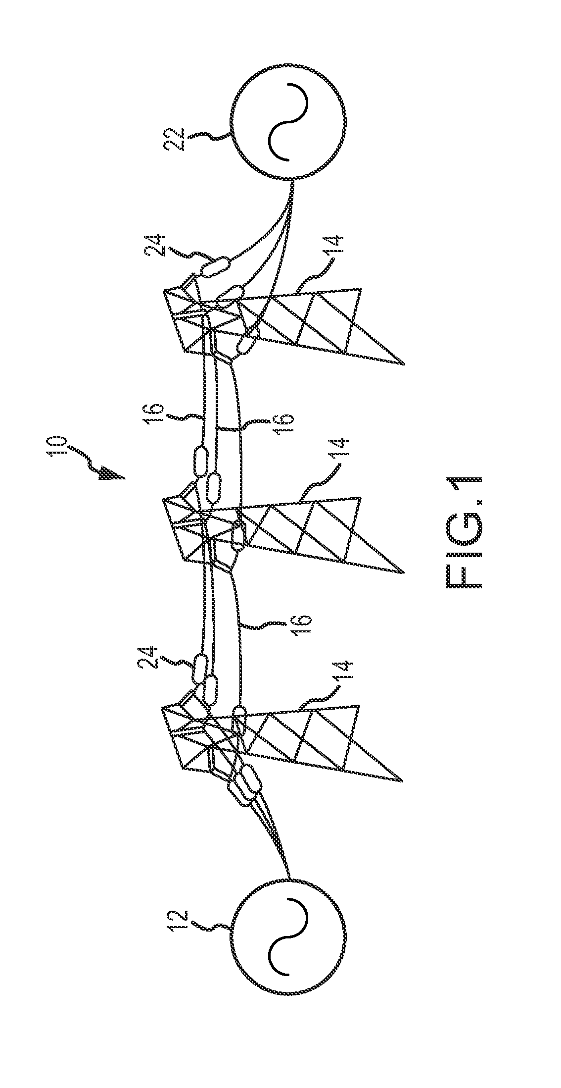
[0072]One embodiment of a power transmission system is illustrated in FIG. 1 as identified by reference numeral 10. The power transmission system 10 includes a plurality of power lines 16 (three in the illustrated embodiment, for providing three-phase power) that extend between an electric power source 12 and a load 22. Any appropriate number of electrical power sources 12 and loads 22 may be associated with the power transmission system 10. A plurality of towers 14 of any appropriate size, shape, and / or configuration may support th...


PUM


Abstract

A device for use in a power transmission system to sense GICs. The device may be a part of a reactance-injecting device on a power line, it may be a standalone device, or it may be a part of another type of device. The device may include a sensor to sense magnetic fields (e.g., a Hall effect sensor). The sensor may be positioned in the air gap of a magnetic core formed concentrically around the power line. The signal from the sensor may be converted to a digital signal and separately processed to determine the magnitude of the AC current and the magnitude of the DC (or quasi-DC) current. If the output signal of another A / C current sensor is available, that output signal may be used to adjust / calibrate the determined magnitude of the DC current. The sensor may communicate with other devices in a network to provide GIC information.

Description

CROSS-REFERENCE TO RELATED APPLICATIONS[0001]This patent application is a non-provisional patent application of, and claims priority to, pending U.S. Provisional Patent Application Ser. No. 61 / 937,220 that is entitled “DETECTION OF GEOMAGNETICALLY-INDUCED CURRENTS WITH POWER LINE-MOUNTED DEVICES,” that was filed on Feb. 7, 2014, and the entire disclosure of which is hereby incorporated by reference in its entirety herein.FIELD[0002]The present invention generally relates to geomagnetically-induced currents on power lines of a power transmission system.BACKGROUND[0003]Power transmission systems are formed of a complex interconnected system of generating plants, substations, and transmission and distribution lines. A significant issue currently plaguing power transmission systems may be characterized as geomagnetically-induced currents (GICs), which are currents induced in a power line due to time-varying magnetic fields external to the Earth and resulting time-varying magnetic fields...

Claims


Application Information

Patent Timeline
IPC IPC(8): G01R19/00G01R21/08
CPCG01R21/08G01R19/0092G01R15/207G01R15/202
Inventor KREIKEBAUM, FRANKPHILLIPSEN, PAULROSS, STUART E.STARODUBTSEV, YULI
Owner SMART WIRES
Learn More