Method and apparatus for stereoscopic imaging

a stereoscopic imaging and stereoscopic technology, applied in the field equipment, can solve the problems of low versatility of stereoscopic imaging methods, high cost, and work with still subjects

Inactive Publication Date: 2015-08-13
MASSACHUSETTS INST OF TECH
View PDF15 Cites 3 Cited by
  • Summary
  • Abstract
  • Description
  • Claims
  • Application Information

AI Technical Summary

Problems solved by technology

Despite the possibly higher cost, the versatility of this method is low.
However the intrinsic drawback of this method is that it only works with still subjects.
Video is not possible, as the method does not work for moving subjects where the position changes drastically between the two independent shots.
Problems of cost, design complexity, alignment and timing synchronization limit the utility of the present methods.

Method used


Image

  • Method and apparatus for stereoscopic imaging
  • Method and apparatus for stereoscopic imaging
  • Method and apparatus for stereoscopic imaging

Examples


Embodiment Construction

[0037]A description of example embodiments of the invention follows.

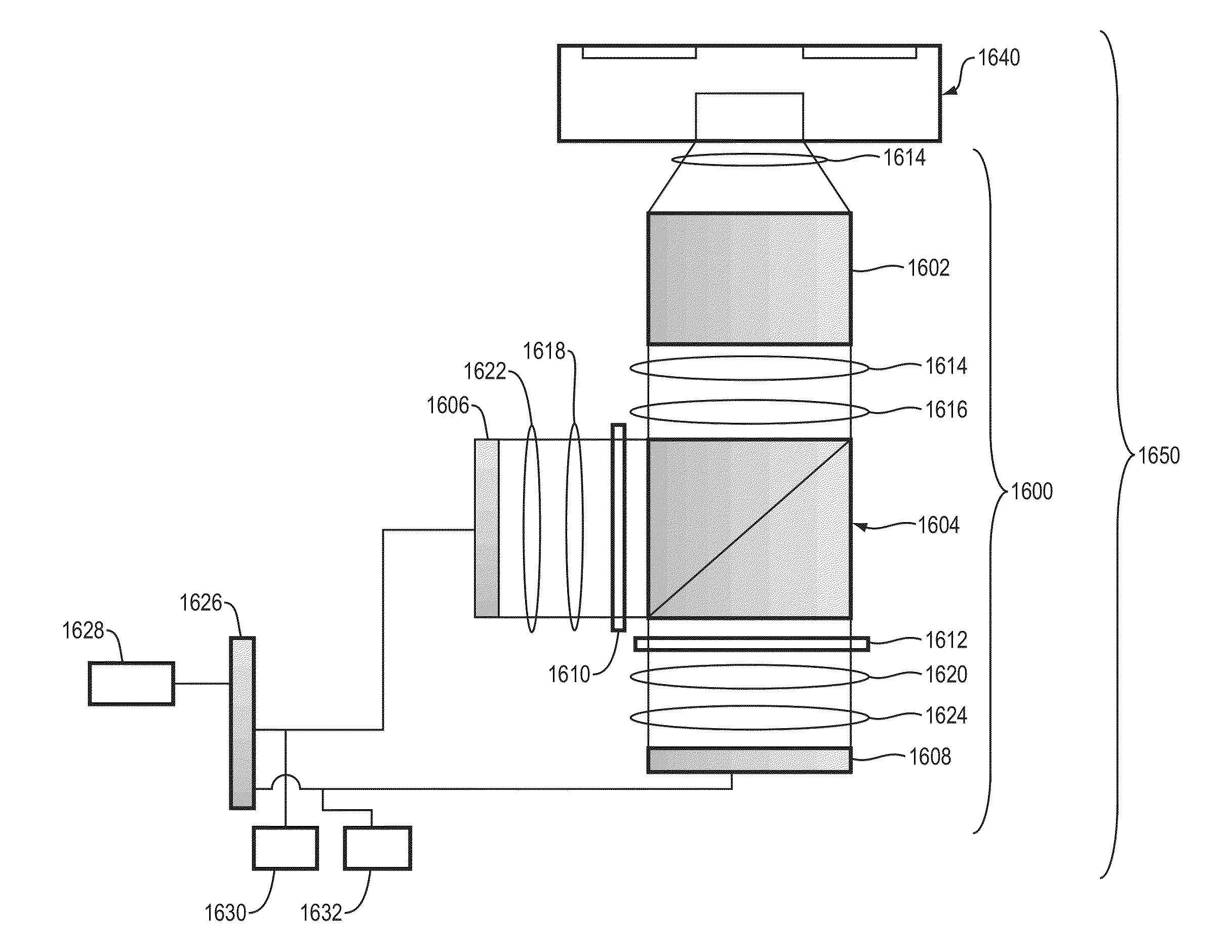
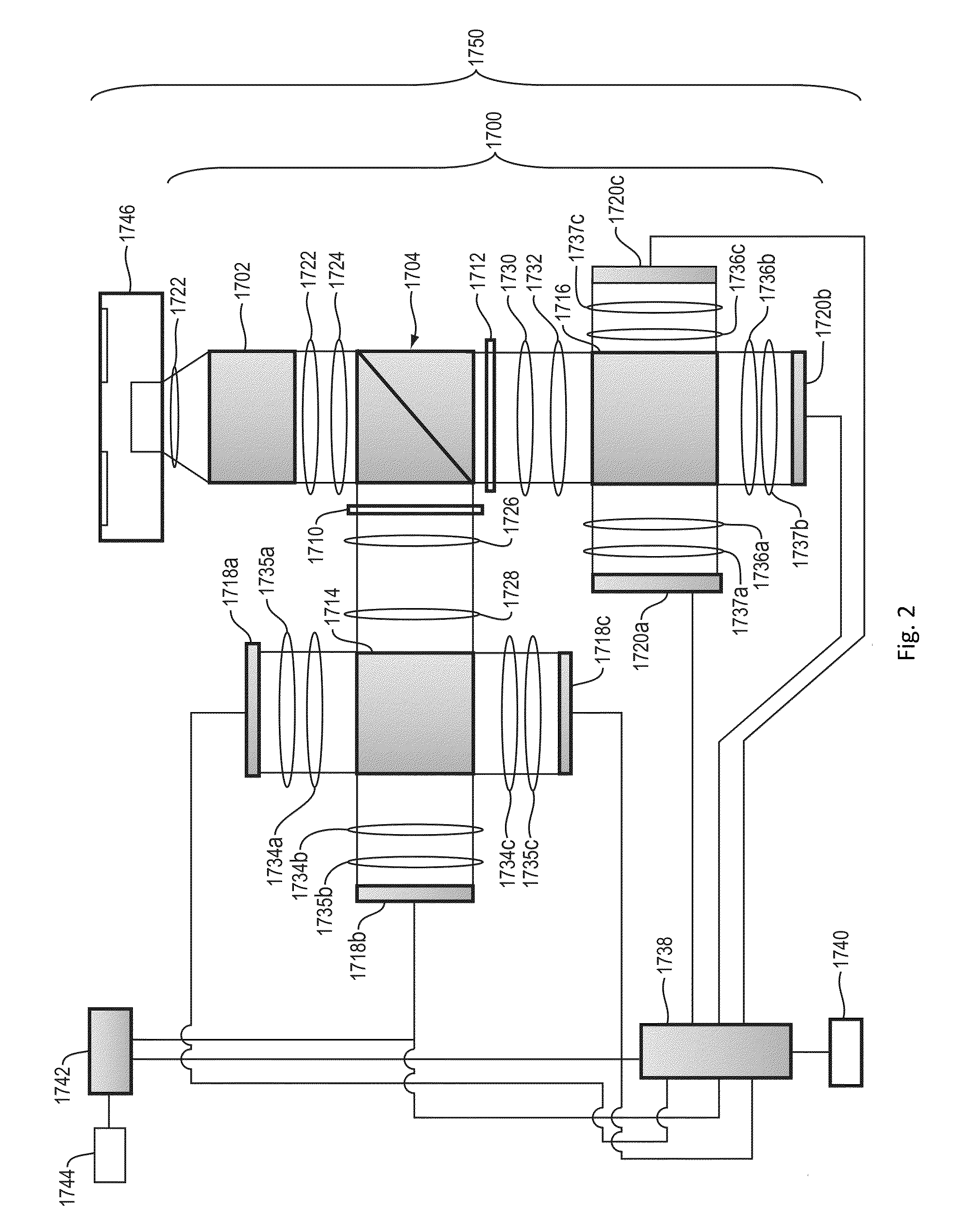
[0038]An example embodiment of the present invention is a device that utilizes color filters or polarization filters to generate two separate beams carrying two separate images of the same object taken from different perspectives. The two perspectives correspond to the human left and right eye perspectives. The two separate beams are directed into a single camera objective (a single shutter camera), resulting in a single image with 3D information encoded in the color or polarization. A significant advantage of such a design is that the same lens is used for each eye perspective, thus permitting to capture a stereoscopic image with a single-shutter image acquisition device. Another advantage is that the images are captured simultaneously and work for both static and moving subjects, allowing 3D video capture. The device can be an attachment to a conventional, i.e. single shutter image capturing device.

[0039]In the ex...


PUM


Abstract

A device is disclosed that utilizes color or polarization to generate two separate images of the same object taken from the two perspectives that correspond to the left and right eyes of an observer. The two separate images are captured through a single camera objective (e.g., a single shutter camera), resulting in a single image with 3D information encoded in the color or polarization. Advantageously, the images are captured simultaneously, permitting obtaining stereoscopic images of both static and moving subjects, allowing 3D video capture. Examples include stereoscopic image acquisition devices that employ two or more image sensors, allowing for an acquisition of a high-definition image. For example, the device can include a trichroic prism and six image sensors, thus capturing left-eye and right-eye sets of color component images.

Description

RELATED APPLICATION[0001]The entire teachings of U.S. application Ser. No. 13 / 762,139, filed Feb. 7, 2013 are incorporated herein by reference.BACKGROUND OF THE INVENTION[0002]Due to the binocular nature of human vision, two eyes “see” from slightly different perspectives. Our brains produce a stereoscopic (“3D”) combination of these images with depth perception. Compared with a projection of a three-dimensional image onto a two-dimensional surface (“2D imaging”), 3D imaging encodes more object position information, particularly depth. Currently 3D imaging requires either two integrated and matched cameras for simultaneous 3D imaging, or repositioning of a single camera for sequential 3D image capture. One method is a dedicated 3D camera with dual lens and dual image sensors. Despite the possibly higher cost, the versatility of this method is low. Another current method for 3D imaging is to acquire two “sequential” images with the same camera, each image acquired at a slightly diffe...

Claims


Application Information

Patent Timeline
Patent Type & Authority Applications(United States)
IPC IPC(8): H04N13/02H04N13/239H04N13/243
CPCH04N13/0239H04N13/211H04N13/243H04N13/218H04N13/239G02B30/36
Inventor LANG, MATTHEW J.
Owner MASSACHUSETTS INST OF TECH
Why Eureka
Try Eureka