Medical stereo observation system

a stereo observation and imaging system technology, applied in medical science, surgery, diagnostics, etc., can solve the problems of ineffective use of image reproducing space situated on the far side (inmost side) of the display panel, image fusion limit by the amount of parallax, etc., to achieve less fatigue of the eyes when the viewer, reduce image fusible range, and high resolution

Active Publication Date: 2010-08-03
OLYMPUS CORP
View PDF16 Cites 46 Cited by
  • Summary
  • Abstract
  • Description
  • Claims
  • Application Information

AI Technical Summary

Benefits of technology

[0019]In the medical stereo observation system according to the present invention, the intersection position shifting means preferably shifts the intersection of the optical axes of the two imaging optical systems so as to cancel a gap between a preset depth position required for the observation in the observation object with a depth and the focal positions, caused by shifting the focal positions of the two imaging optical systems in association with the magnification change of the variable magnification optical systems.
[0027]According to the present invention, even when a part required for the observation is a narrow hole-like domain, an image fusible range can be effectively utilized and fatigue given to the viewer is lessened as far as possible so that a magnified image with high resolution can be observed stereoscopically. Such a medical stereo observation system is obtained.

Problems solved by technology

Consequently, in a stereoscopic space reproduced on the display panel, a space limit by the amount of parallax that is an image fusion limit occurs.
When the hole-like part to be operated is observed in the conventional stereo observation system, the part to be operated is reproduced only in front of the display panel, and thus an image reproducing space situated on the far side (the inmost side) of the display panel cannot be effectively used.
In addition, when a deep hole such as that reaching a deep portion of the brain is observed, an image close to the entrance of the hole is reproduced at a position where the image fusion limit is exceeded, and hence this is responsible for the fatigue of the eyes when the viewer makes the observation.
In the stereo observation system, when electronic zoom is applied during the observation of the observation object with a depth, the amount of parallax on the display panel surface of the observation object at a position separating from the focal positions of the imaging optical systems for left and right eyes, imaged by the imaging section is increased in accordance with the electronic zoom, and the image fusion of the viewer becomes difficult.

Method used


Image

  • Medical stereo observation system
  • Medical stereo observation system
  • Medical stereo observation system

Examples


first embodiment

[0105]FIG. 10 shows a medical stereo observation system according to this embodiment.

[0106]The stereo observation system of the first embodiment includes stereo imaging units such as an electronic image surgical microscope 85 and an electronic image stereoendoscope 86; an image signal processing unit 87; light source units 88 supplying illumination light to the stereo imaging units; and one of various stereo display units denoted by symbols A-E in the figure.

[0107]The display unit denoted by symbol A in the figure indicates a parallax barrier system no-spectacles stereo display device. Left and right images are arranged in a strip-like array on an LCD 89 and a barrier 90 is placed before the images to introduce selectively corresponding images into the left and right eyes of a viewer 93 so that the stereo observation can be made.

[0108]The display unit by B indicates a polarizing spectacles type stereo display device. A polarizing shutter 92 converting in turn a polarizing direction ...

second embodiment

[0116]FIG. 13 shows a medical stereo observation system according to this embodiment.

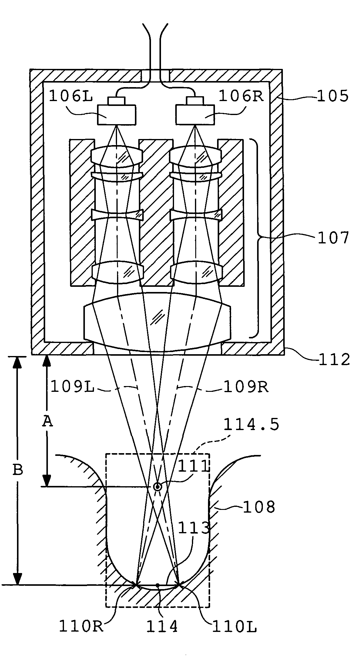
[0117]The stereo observation system of the second embodiment comprises an electronic image surgical microscope 135 constructed as an imaging unit, a holding arm 135.5 holding the electronic image surgical microscope, a virtual image observation type stereo display unit 136, a holding arm 136.5 holding the stereo display unit, a light source unit 137 providing the electronic image surgical microscope with illumination light, an image signal processing unit 138 processing an image signal produced by the electronic image surgical microscope, and an image signal supplying unit 139 supplying the image signal to the stereo display unit. Images of a part 140 to be operated that mutually have parallax are produced by the electronic image surgical microscope 135 and are displayed on the stereo display unit 136 through the image signal processing unit 138 and the image signal supplying unit 139. A viewer 141 ...

third embodiment

[0124]FIG. 17 shows the medical stereo observation system of this embodiment. The stereo observation system of the third embodiment comprises an electronic image stereoendoscope 165 constructed as an imaging unit, a holding arm 166 holding the electronic image stereoendoscope, a projection type stereo display unit 167, a holding arm 168 holding the stereo display unit, a light source unit 169 providing the electronic image stereoendoscope with illumination light, an image signal processing unit 170 processing an image signal produced by the electronic image stereoendoscope, and an image signal supplying unit 171 supplying an image signal to the stereo display unit. The electronic image stereoendoscope 165 produces images of a part to be operated that mutually have parallax, and the images are displayed on the stereo display unit 167 through the image signal processing unit 170 and the image signal supplying unit 171. A viewer 172 observes the images displayed on the stereo display u...


PUM


Abstract

A medical stereo observation system includes a stereo imaging unit producing a first image for a left eye and a second image for a right eye that mutually have parallax and a stereo display unit capable of displaying stereoscopically the images produced by the stereo imaging unit. The stereo imaging unit has a first imaging optical system producing the first image for the left eye and a second imaging optical system producing the second image for the right eye, and focal positions of these imaging optical systems are located far away from the intersection of optical axes of the imaging optical systems, viewed from the stereo imaging unit. Whereby, a large-depth space can be comfortably observed in a wide range and a viewer can observe an observation object without bringing about a feeling of fatigue.

Description

[0001]This application claims benefits of Japanese Application No. 2005-261670 filed in Japan on Sep. 9, 2005 and No. 2005-266808 filed in Japan on Sep. 14, 2005, the contents of which are hereby incorporated by reference.BACKGROUND OF THE INVENTION[0002]1. Field of the Invention[0003]This invention relates to a medical stereo observation system suitable for the stereo observation of a medical image used in a surgical operation, and particularly in neurosurgery, otolaryngology, orthopedic and plastic surgery, obstetrics and gynecology, or ophthalmology.[0004]2. Description of Related Art[0005]In recent years, the technique of using the medical stereo observation system, such as a stereoendoscope or a surgical (stereo) microscope, has been popularized in the field of medical treatment (notably surgery). In general, the medical stereo observation system is of a binocular type, and includes a stereo imaging unit incorporating imaging optical systems and image sensors to form left and r...

Claims


Application Information

Patent Timeline
Patent Type & Authority Patents(United States)
IPC IPC(8): G02B21/22G02B21/00H04N13/239
CPCA61B1/00193G02B21/22G02B27/2228H04N13/0239H04N13/04A61B19/5223H04N13/0409H04N13/0429H04N13/044H04N13/0459A61B90/20H04N13/344H04N13/30H04N13/31H04N13/332H04N13/363H04N13/239G02B30/34
Inventor HIROSE, KENJIISHIKAWA, TOMONORIMORITA, KAZUO
Owner OLYMPUS CORP
Why Eureka
Try Eureka