Image display device and image display method

a display device and image technology, applied in image enhancement, image analysis, instruments, etc., can solve the problems of double-circulation of the boundary, inability to see far objects clearly,

Inactive Publication Date: 2015-08-20
SOVEREIGN PEAK VENTURES LLC
View PDF14 Cites 60 Cited by
  • Summary
  • Abstract
  • Description
  • Claims
  • Application Information

AI Technical Summary

Benefits of technology

[0070]According to the present invention, a near object which cannot be seen clearly due to ametropia such as presbyopia can be seen clearly when observed in a state of overlapping a correction image for correcting blurring due to the pre

Problems solved by technology

If the presbyopia spectacles are used, a near object can be seen clearly, but there is a problem in that a far object cannot be seen clearly.
In addition, in order to solve this problem, the presbyopia spectacles are worn when a near object is seen, and the presbyopia s

Method used


Image

  • Image display device and image display method
  • Image display device and image display method
  • Image display device and image display method

Examples


embodiment 1

[0090]Hereinafter, Embodiment 1 of the present invention will be described with reference to the drawings.

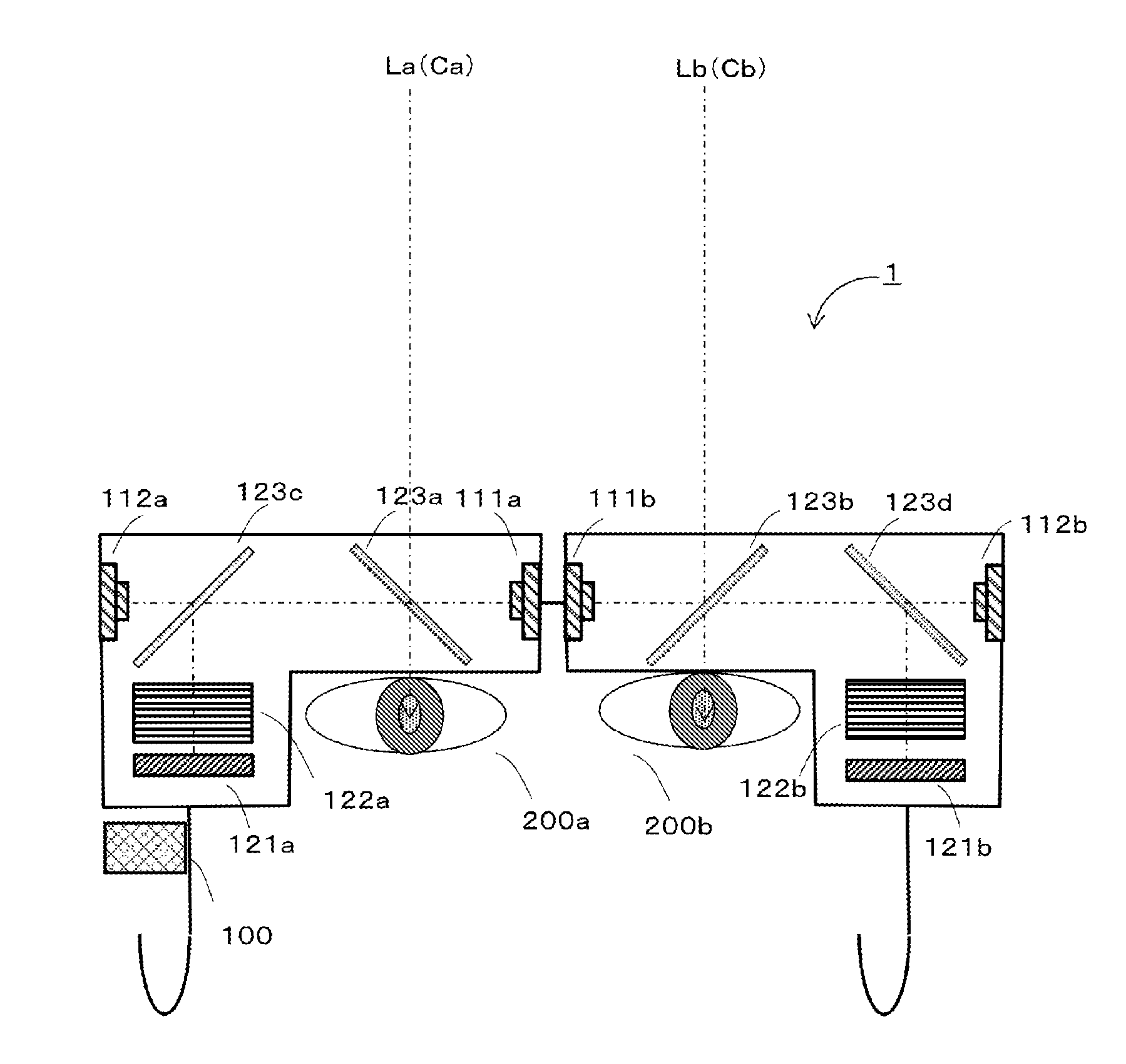
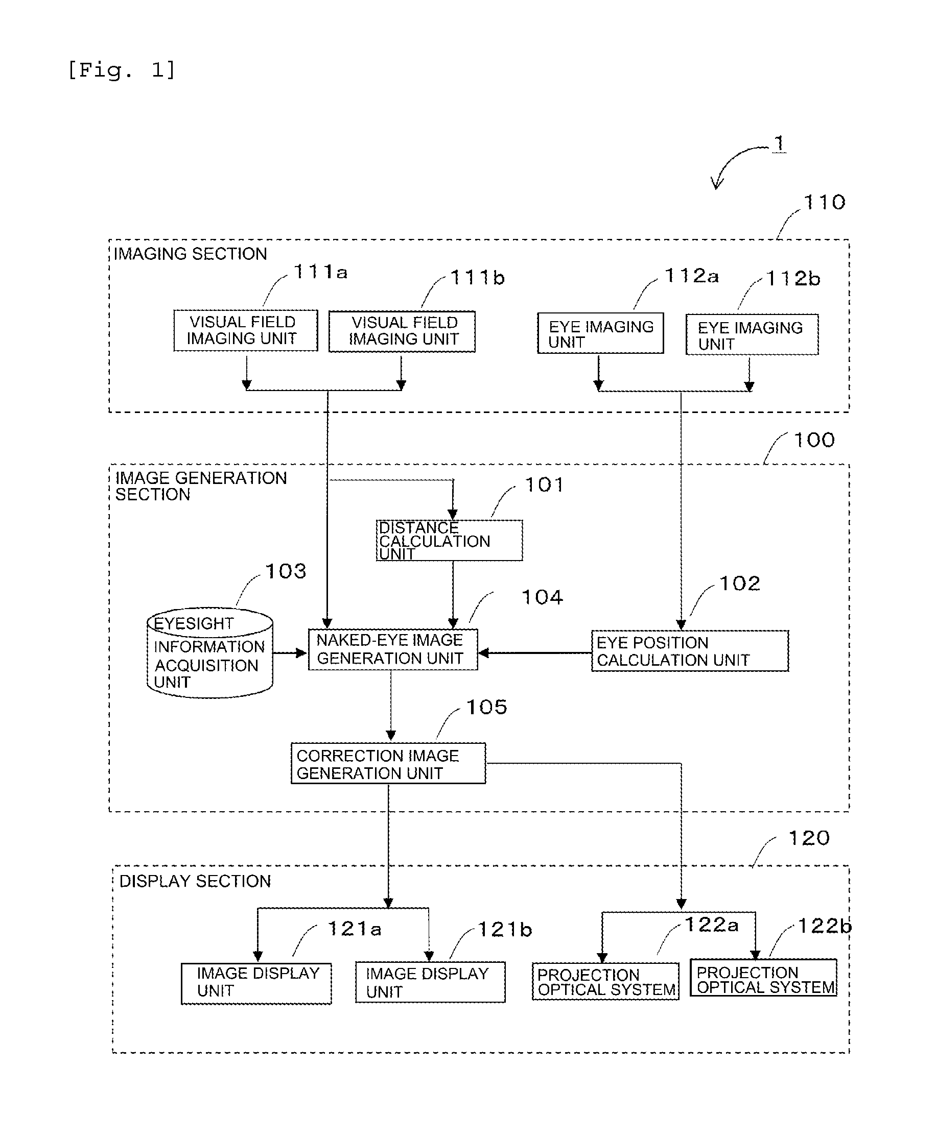
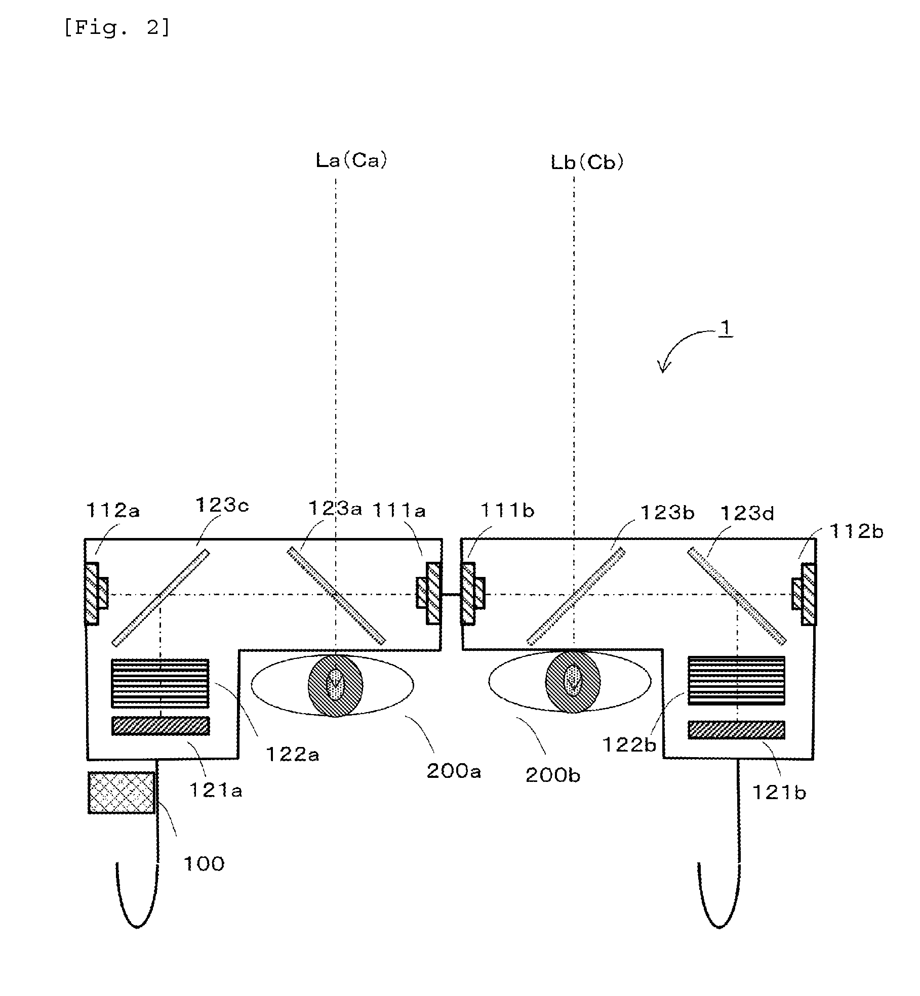
[0091]FIG. 1 is a block diagram illustrating a configuration of an image display device 1 in Embodiment 1. As illustrated in FIG. 1, the image display device 1 in Embodiment 1 includes an imaging section 110, an image generation section 100, and a display section 120. The imaging section 110 includes left and right two visual field imaging units 111a and 111b, and left and right two eye imaging units 112a and 112b. The image generation section 100 includes a distance calculation unit 101, an eye position calculation unit 102, an eyesight information acquisition unit 103, a naked-eye image generation unit 104, and a correction image generation unit 105. The display section 120 includes left and right two image display units 121a and 121b, and left and right two projection optical systems 122a and 122b. In addition, the subscripts a to d are used to differentiate the same members ...

embodiment 2

[0173]In the above-described Embodiment 1 of the present invention, the image display device 1 is configured to include the imaging section 110 and the display section 120 for both of the left and right eyes. In contrast, in Embodiment 2, a description will be made of an display device 2 having a configuration in which the visual field imaging unit 111, the eye imaging unit 112, the image display unit 121, and the projection optical system 122 for either one of the left and right eyes are excluded.

[0174]FIG. 12 is a block diagram illustrating a configuration of the image display device 2 of Embodiment 2; FIG. 13 is a schematic diagram illustrating an arrangement of an optical system of the image display device 2 of Embodiment 2; and FIG. 14 is a flowchart illustrating an operation procedure of an image generation section.

[0175]The distance calculation unit 101 (a portion performing the distance calculation step S401) of Embodiment 1 receives two visual field images captured by the l...

embodiment 3

[0188]In the above-described Embodiments 1 and 2, assuming that a gaze point of the user changes, the image generation section 100 estimates the gaze point of the user, generates a correction image on the basis of the estimated value, and controls a distance of the projection optical system.

[0189]On the other hand, as a method of using presbyopia spectacles in the related art, generally, assuming that a distance to a book when a certain user is reading the book or a distance to a display when the user performs work with a PC is constant, spectacles with a degree which matches the distance are used. Therefore, in Embodiment 3, a description will be made of a configuration of an image display device in a case where a distance for correcting presbyopia is assumed to be constant.

[0190]In Embodiments 1 and 2, the image display devices 1 and 2 include the eye imaging unit 112 and the eye position calculation unit 102, whereas, in an image display device 3 of Embodiment 3, the eye imaging ...


PUM


Abstract

This invention solves the problem that objects in the field of view of reading glasses using multifocal lenses for correcting ocular refractive errors such as presbyopia appear distorted. This image display device is provided with the following: a distance computation unit that computes the distance to a subject in a field-of-view image; a visual-acuity-information acquisition unit that stores visual-acuity information for the user in advance; a corrected-image generation unit that generates and outputs a corrected image on the basis of the field-of-view image and an eye image generated from the field-of-view image, the distance information, and the visual-acuity information; and a display unit that displays the corrected image by superimposing same onto the user's field of view. Since the corrected image is superimposed without the use of lenses, lenses being the cause of the abovementioned distortion, the user can see close objects clearly.

Description

TECHNICAL FIELD[0001]The present invention relates to an image display device, and particularly to a head mounted type or spectacle type image display device which overlaps an image displayed on a display section mounted on a user's head or the like on a user's visual field so as to enable the user to see an object clearly, targeting a person which cannot see an object clearly due to ametropia such as presbyopia, myopia, or hyperopia.BACKGROUND ART[0002]Due to the abnormality of a refractive index of the lens or deterioration in adjustment performance thereof, the abnormality of a form of the eyeball, or the like, ametropia of an eye such as presbyopia, myopia, or hyperopia occurs. Among them, the presbyopia refers to a state in which adjustment performance of the lens is weakened by aging and thus the lens cannot focus on a near object. In order to correct the presbyopia, presbyopia spectacles formed of convex lenses are mainly used. If the presbyopia spectacles are used, a near ob...

Claims


Application Information

Patent Timeline
IPC IPC(8): G06T19/00G06T5/00G02C11/00
CPCG06T19/006G02C11/10G06T2207/30201G06T2207/10012G06T5/006G06T2207/30041G02B27/017G02B2027/011G02B2027/0138G02B2027/014G02B2027/0187G02B27/0093
Inventor NOBORI, KUNIOMARUYAMA, AYAKOKATO, YUMIKOINOUE, TSUYOSHI
Owner SOVEREIGN PEAK VENTURES LLC
Why Eureka
Try Eureka